


- 9 -
English
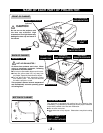
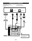
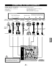
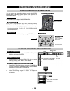
CONNECTING TO VIDEO EQUIPMENT
S–VIDEO
R–AUDIO–L
VIDEO/Y Cb/Pb Cr/Pr
VIDEO/Y Cb/Pb Cr/Pr
RESET
CONTROL PORT
AUDIO 1
AUDIO 2
ANALOG
DIGITAL(DVI-D)
INPUT 1
INPUT 2
INPUT 3
R/C JACK
GBRH/V V
(
MONO
)
Video Source (example)
Video Cassette Recorder
Video Disc Player
S-VIDEO
Cable ✽
Terminals
of a Projector
S-VIDEO
Output
Cables used for connection (✽ = Cable is not supplied with this projector.)
Audio Cable
(RCA x 2) ✽
AUDIO IN
S-VIDEO
Y - Cb/Pb - Cr/Pr
VIDEO
Component video output equipment.
(such as DVD player or high-definition TV source.)
Composite
Video Output
Component Video
Output
(Y, Cb/Pb, Cr/Pr)
Component Video
Output
(Y, Cb/Pb, Cr/Pr)
Y - Cb/Pb - Cr/Pr
Video Cables
(
RCA x 1 or
RCA x 3) ✽
BNC Cable ✽
Audio
Output
Composite
Video Output
VIDEO
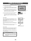
• Video Cable (RCA x 1 or RCA x 3) ✽
• BNC Cable ✽
• S-VIDEO Cable ✽
• DVI-Digital Cable (for Single Link T.M.D.S.) ✽
• Audio Cable (RCA x 2) ✽
• HDB 15 pin-SCART 21 pin Cable ✽
RGB Scart
21-pin Output
HDB 15 pin-
SCART 21 pin
Cable ✽
INPUT TERMINAL (ANALOG)
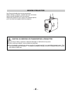
Note:
When connecting the cable, the power cords of
both the projector and the external equipment
should be disconnected from AC outlet.
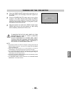
Digital Output
(HDCP compatible)
DVI-Digital
Cable
✽
INPUT TERMINAL
(DIGITAL)