


Stacking Frame Installation Instructions
013-100342-01 (Rev.1) (08/06) 5 of 12 pages
3. Loosen the nuts on the rear stacking legs to provide lateral movement for easier
alignment with the stacking mounts on the other projector.
For upright position:
Release the rear stacking legs on the top projector.
For inverted position:
Release the rear stacking legs on the bottom projector.
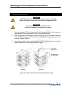
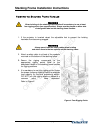
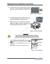
4. Remove the safety pins from each stacking mount in order to fit the stacking legs
into the stacking mounts. Refer to Figure 3.
For upright position:
Remove the pins from the mounts on the bottom projector.
For inverted position:
Remove the pins from the mounts on the top projector.
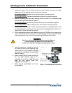
5. With one person positioned on each side of the projector, lift the top projector onto
the bottom projector, aligning all three stacking points between the projectors. The
legs should fit inside the stacking mounts.
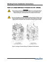
6. Turn the adjusting wheel on each stacking mount until the hole in the top portion
of the mount lines up with the hole in the stacking leg. To make alignment easier
insert a screwdriver into one of the holes and use it to align the two holes.
WARNING
Step 7 is a critical safety procedure that must be observed.
Failure to engage the safety locks could cause the
projectors to separate, resulting in possible injury or death.
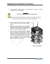
7. Insert the safety pin through the holes in
the stacking mounts and stacking legs.
Ensure each pin is fully inserted to engage
the safety lock and secure the projectors.
Refer to Figure 3.
8. Before hoisting, firmly tighten the nuts on
the two rear stacking legs. If the
projectors are ready for image alignment
keep the nuts slightly loose until
alignment is complete.
9. When required, repeat Steps 1 to 8 for the
third projector.
Figure 3. Stacking Mount Components
OFFICIALLY RELEASED
Document Control
September 8, 2006