


manufacturer patches and
utility software are
installed.
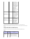
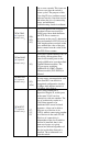
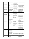
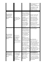
Xircom XE2000
PCMCIA NIC
Does not
autonegotiate to 100
Mbps, full−duplex.
NIC only
autonegotiates to 100
Mbps, half−duplex.
Known limitation of
XE2000 NIC. Refer to
the XE2000 release
notes.
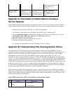
Appendix A: Information to Gather Before Creating a
Service Request
If the troubleshooting procedure outlined in this document does not resolve your issue, you need to create a
service request with Cisco Technical Support. Before you create a service request, gather this information:
Identify the specific problem with NIC−to−switch interoperability.
For example, is the problem only with DHCP, Novell IPX, login, or performance?
1.
Issue the show tech−support command from all affected Cisco devices, if applicable; or, issue the
show module, show config, show version, or the show port commands.
2.
Know the make and model of the NIC.3.
Know the operating system and the NIC driver version.4.
Verify the consistency of the problem.
For example, does the problem occur across multiple Catalyst switches?
5.
Appendix B: Understanding How Autonegotiation Works
Autonegotiation uses a modified version of the link integrity test that is used for 10BASE−T devices to
negotiate speed and exchange other autonegotiation parameters. The original 10BASE−T link integrity test is
referred to as Normal Link Pulse (NLP). The modified version of the link integrity test for 10/100 Mbps
autonegotiation is referred to as FLP. The 10BASE−T devices expect a burst pulse every 16 (+/− 8)
milliseconds (msec) as part of the link integrity test. FLP for 10/100 Mbps autonegotiation sends these bursts
every 16 (+/− 8) msec with the additional pulses every 62.5 (+/− 7) microseconds. The pulses within the burst
sequence generate code words that are used for compatibility exchanges between link partners. This process
of FLP used in autonegotiation maintains backward compatibility with existing 10BASE−T connections, with
the pulse burst every 16 (+/− 8) msec to comply with the link integrity test for normal 10BASE−T hardware.
If a device sends FLP and only receives NLP, the hardware immediately ceases transmission of the FLP and
enables the standard 10BASE−T hardware to continue 10BASE−T operation.
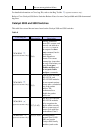
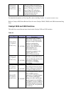
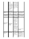
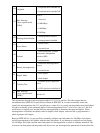
This table describes the possible programmable options of the control register for a FastEthernet interface.
These options determine how the FastEthernet interface functions when connected to a link partner. The 0 in
the Bits column refers to the programmable register address, and the decimal number after the 0 refers to the
bit placement within the 16−bit register.
Table 12Physical Interface (PHY) Control Register Programmable Options
Bits
Name Description
0.15
Reset
1 = PHY reset
0 = normal mode