


14
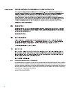
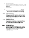
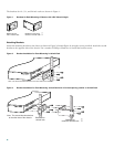
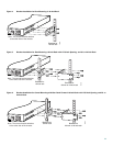
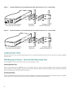
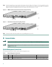
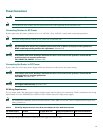
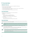
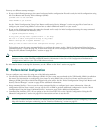
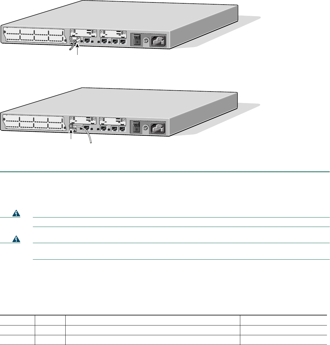
Step 3 Attach the ground lug or ring terminal to the chassis as shown in Figure 10 or Figure 11. For the ground lug, use the
two screws with captive locking washers provided. For a ring terminal, use one of the screws provided. Use a number 2
Phillips screwdriver, and tighten the screws to a torque of 8 to 10 in-lb (0.9 to 1.1 N-m).
Figure 10 NEBS-Compliant Chassis Ground Connection Using Ground Lug
Figure 11 Chassis Ground Connection Using Ring Terminal
Step 4 Connect the other end of the ground wire to a grounding point at your site.
4 Connect Cables
Warning
Do not work on the system, or connect or disconnect cables during periods of lightning activity.
Statement 1001
Warning
Before opening the chassis, disconnect the telephone-network cables to avoid contact with telephone-network
voltages.
Statement 1004
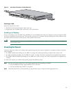
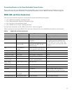
System Management Connections
The connections described in Table 1 provide system management access.
Table 1 System Management Connections
Port Color Connected To: Cable
Console Light blue PC or ASCII terminal communication port (usually labeled COM) RJ-45-to-DB-9 adapter cable
Auxiliary Black Modem for remote access RJ-45-to-DB-25 adapter cable
S
E
E
M
A
N
U
A
L
B
E
F
O
R
E
IN
S
T
A
L
L
A
T
IO
N
S
E
R
I
A
L
1
S
E
R
IA
L
0
C
O
N
N
C
O
N
N
W
I
C
2
A
/S
S
E
E
M
A
N
U
A
L
B
E
F
O
R
E
I
N
S
T
A
L
L
A
T
I
O
N
S
E
R
I
A
L
1
S
E
R
IA
L
0
C
O
N
N
C
O
N
N
W
IC
2
T
Cisco 2611
100-240V– 1A
50/60 Hz 47 W
W0
AUX
CONSOLE
ETHERNET 0
ACT
LINK
ACT
ETHERNET 1
LINK
W1
36454
Ground lug
103057
S
E
E
M
A
N
U
A
L
B
E
F
O
R
E
IN
S
T
A
L
L
A
T
IO
N
S
E
R
IA
L
1
S
E
R
IA
L
0
C
O
N
N
C
O
N
N
W
IC
2
A
/S
S
E
E
M
A
N
U
A
L
B
E
F
O
R
E
IN
S
T
A
L
L
A
T
IO
N
S
E
R
IA
L
1
S
E
R
IA
L
0
C
O
N
N
C
O
N
N
W
IC
2
T
Cisco 2611
100-240V– 1A
50/60 Hz 47 W
W0
AUX
CONSOLE
ETHERNET 0
ACT
LINK
ACT
ETHERNET 1
LINK
W1
Ring terminal