


24
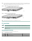
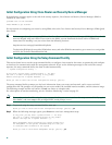
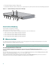
• First built-in Ethernet interface—Ethernet 0/0
• Second built-in Ethernet interface—Ethernet 0/1, or optionally in Cisco 2612 and Cisco 2613 only: Token Ring interface 0/0
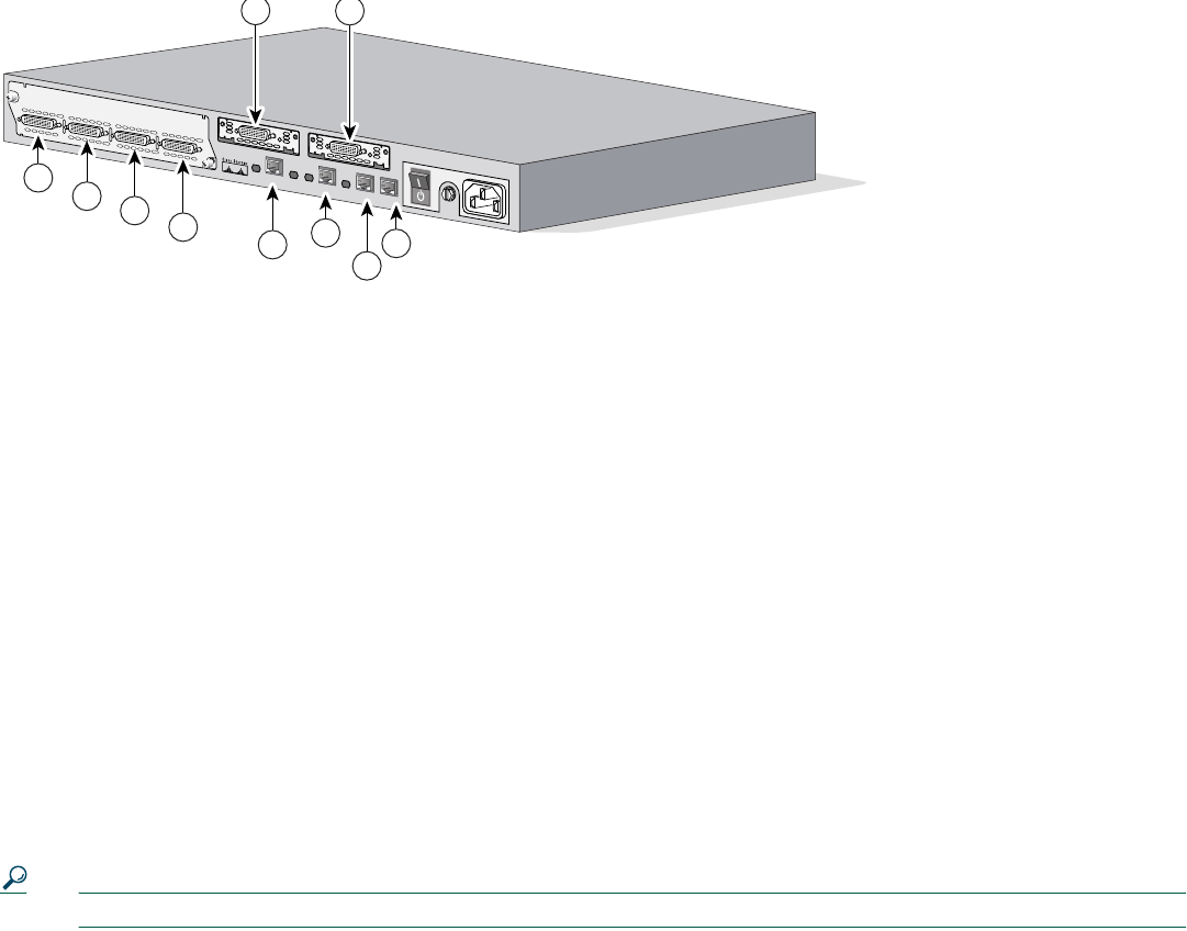
Figure 13 Interface Numbering in Chassis with 1-RU Height
Voice Interface Numbering
Voice interfaces are numbered as follows:
chassis-slot/voice-module-slot/voice-interface
If a 4-channel voice network module is installed in chassis slot 1, the voice interfaces are:
• 1/0/0—Chassis slot 1/Voice module slot 0/Voice interface 0
• 1/0/1—Chassis slot 1/Voice module slot 0/Voice interface 1
• 1/1/0—Chassis slot 1/Voice module slot 1/Voice interface 0
• 1/1/1—Chassis slot 1/Voice module slot 1/Voice interface 1
8 Where to Go Next
For additional detailed configuration procedures, refer to the appropriate Cisco 2600 series documentation or Cisco IOS
software documentation, available online on Cisco.com:
Tip See the “Obtaining Additional Publications and Information” section on page 27 for help in locating these documents.
To access documentation on Cisco.com:
For Cisco 2600XM series platform documentation, start on Cisco.com at http://www.cisco.com, and select
Products & Services > Routers > Cisco 2600 Series Multiservice Platforms > Technical Documentation > Document type >
Document.
For Cisco IOS software documentation, start on Cisco.com at http://www.cisco.com, and select Products & Services > IOS
Software > Cisco IOS Software Releases > Your Cisco IOS software release.
To get updated information about platform support for features, select Feature Navigator II, if you have an account on
Cisco.com. You can also access Feature Navigator II at http://www.cisco.com/go/fn.
28308
Cisco 2612
10
0-2
4
0V
– 1
A
50
/6
0
H
z 4
7
W
W
1
CN/LP
2
10
3
RXCRXD
TXCTXD
CN/LPRXC
RXD
TXC
TXD CN/LP
RXCRXDTXC
TX
D
CN/LPRXCRXDTXC
TXD
E
N
SERIAL
A/S
W
0
S
E
R
I
A
L
C
O
N
N
W0
S
ER
IA
L
C
ON
N
AUX
CONSOLE
ETHERNET 0/0
ACT
LINK
ACT
TOKEN RING 0/0
LINK
W0
3
4
5
6
7
8
9
10
1
2