Cisco Systems, Inc.
All contents are Copyright © 1992–2003 Cisco Systems, Inc. All rights reserved. Important Notices and Privacy Statement.
Page 12 of 15
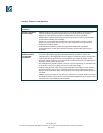
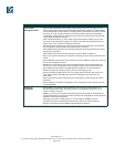
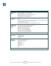
Standards • IEEE 802.1x support
• IEEE 802.3x full duplex on 10BASE-T and 100BASE-TX ports
• IEEE 802.1D Spanning-Tree Protocol
• IEEE 802.1p class-of-service (CoS) prioritization
• IEEE 802.1Q VLAN
• IEEE 802.3 10BASE-T specification
• IEEE 802.3u 100BASE-TX specification
• IEEE 802.3ad
• IEEE 802.3z 1000BASE-X specification
Connectors
and cabling
• 10BASE-T ports: RJ-45 connectors, two-pair Category 3, 4, or 5 unshielded twisted-pair (UTP)
cabling
• 100BASE-TX ports: RJ-45 connectors; two-pair Category 5 UTP cabling
• 1000BASE-SX ports: MT-RJ connectors, up to 1800 feet (550 meters) cable distance for 50/125
or up to 900 ft (275 m) cable distance for 62.5/125 micron multimode fiber-optic cabling
• Management console port: 8-pin RJ-45 connector, RJ-45-to-DB9 adapter cable for PC
connections; for terminal connections, use RJ-45-to-DB25 female data-terminal-equipment
(DTE) adapter (can be ordered separately, Cisco part number ACS-DSBUASYN=)
MT-RJ patch
cables for
Cisco Catalyst
2950SX-24
Switch
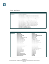
Type of cable, Cisco part number:
• 1-meter MT-RJ-to-SC multimode cable, CAB-MTRJ-SC-MM-1M
• 3-meter MT-RJ-to-SC multimode cable, CAB-MTRJ-SC-MM-3M
• 5-meter MT-RJ-to-SC multimode cable, CAB-MTRJ-SC-MM-5M
• 1-meter MT-RJ-to-ST multimode cable, CAB-MTRJ-ST-MM-1M
• 3-meter MT-RJ-to-ST multimode cable, CAB-MTRJ-ST-MM-3M
• 5-meter MT-RJ-to-ST multimode cable, CAB-MTRJ-ST-MM-5M
Power
connectors
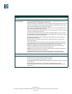
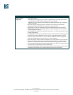
Customers can provide power to a switch by using the internal power supply, the Cisco RPS 675
Redundant Power System. The connectors are located at the back of the switch.
Internal power supply connector:
• The internal power supply is an auto-ranging unit.
• The internal power supply supports input voltages between 100 and 240 VAC.
• Use the supplied AC power cord to connect the AC power connector to an AC power outlet.
Cisco RPS 675 connector:
• The connector offers connection for an optional Cisco RPS 675 that uses AC input and supplies
DC output to the switch.
• The connector offers a 675W redundant power system that supports six external network
devices and provides power to one failed device at a time.
• The connector automatically senses when the internal power supply of a connected device
fails and provides power to the failed device, preventing loss of network traffic.
• Attach only the Cisco RPS 675 (Model PWR675-AC-RPS-NI=) to the redundant power supply
receptacle with this connector.
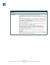
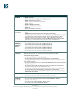
Indicators • Per-port status LEDs: link integrity, disabled, activity, speed, and full-duplex indications
• System status LEDs: system, RPS, and bandwidth-utilization indications
Dimensions
and weight
(H x W x D)
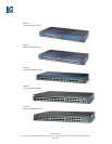
• 1.72 x 17.5 x 9.52 in. (4.36 x 44.45 x 24.18 cm) (Cisco Catalyst 2950SX-24, 2950-24, 2950-12)
• 1.72 x 17.5 x 13 in. (4.36 x 44.45 x 33.02 cm) (Cisco Catalyst 2950SX-48, 2950T-48)
• 1 RU high (1.72 in./4.36 cm)
• 6.5 lb (3.0 kg) (Cisco Catalyst 2950SX-24, 2950-24, 2950-12)
• 10.b lb (4.8 kg) (Cisco Catalyst 2950SX-48, 2950T-48)
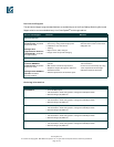
Feature Description/Part Numbers


