


10-6
Cisco Catalyst Blade Switch 3130 for Dell Software Configuration Guide
OL-13270-01
Chapter 10 Configuring Interface Characteristics
Understanding Interface Types
When you configure an EtherChannel, you create a port-channel logical interface and assign an interface
to the EtherChannel. For Layer 3 interfaces, you manually create the logical interface by using the
interface port-channel global configuration command. Then you manually assign an interface to the
EtherChannel by using the channel-group interface configuration command. For Layer 2 interfaces, use
the channel-group interface configuration command to dynamically create the port-channel logical
interface. This command binds the physical and logical ports together. For more information, see
Chapter 37, “Configuring EtherChannels and Link-State Tracking.”
10-Gigabit Ethernet Interfaces
The switch has two 10-Gigabit Ethernet module slots. For uplink connections to other switches and
routers, use the Cisco TwinGig Converter Modules.
A 10-Gigabit Ethernet interface operates only in full-duplex mode. The interface can be configured as a
switched or routed port.
For more information about the Cisco TwinGig Converter Module, see the switch hardware installation
guide and your transceiver module documentation.
Connecting Interfaces
Devices within a single VLAN can communicate directly through any switch. Ports in different VLANs
cannot exchange data without going through a routing device. With a standard Layer 2 switch, ports in
different VLANs have to exchange information through a router.
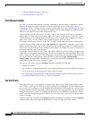
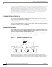
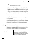
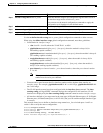
By using the switch with routing enabled, when you configure both VLAN 20 and VLAN 30 with an
SVI to which an IP address is assigned, packets can be sent from Blade Server A to Blade Server B
directly through the switch with no need for an external router (Figure 10-1).
Figure 10-1 Connecting VLANs with the Blade Switch
When the IP services feature set is running on the switch or the stack master, the switch uses two
methods to forward traffic between interfaces: routing and fallback bridging. If the IP base feature set is
on the switch or the stack master, only basic routing (static routing and RIP) is supported. Whenever
Blade
server A
Blade
server B
SVI 1
1
72.20.128.1 172.20.129
.1
SVI 2
Layer 3 switch
with routing enabled
VLAN 20 VLAN 30
2
01763