


10-7
Cisco Catalyst Blade Switch 3130 for Dell Software Configuration Guide
OL-13270-01
Chapter 10 Configuring Interface Characteristics
Using Interface Configuration Mode
possible, to maintain high performance, forwarding is done by the switch hardware. However, only IPv4
packets with Ethernet II encapsulation are routed in hardware. Non-IP traffic and traffic with other
encapsulation methods are fallback-bridged by hardware.
• The routing function can be enabled on all SVIs and routed ports. The switch routes only IP traffic.
When IP routing protocol parameters and address configuration are added to an SVI or routed port,
any IP traffic received from these ports is routed. For more information, see Chapter 38,
“Configuring IP Unicast Routing,” Chapter 44, “Configuring IP Multicast Routing,” and
Chapter 45, “Configuring MSDP.”
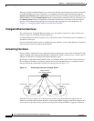
• Fallback bridging forwards traffic that the switch does not route or traffic belonging to a nonroutable
protocol, such as DECnet. Fallback bridging connects multiple VLANs into one bridge domain by
bridging between two or more SVIs or routed ports. When configuring fallback bridging, you assign
SVIs or routed ports to bridge groups with each SVI or routed port assigned to only one bridge
group. All interfaces in the same group belong to the same bridge domain. For more information,
see Chapter 46, “Configuring Fallback Bridging.”
Using Interface Configuration Mode
The switch supports these interface types:
• Physical ports—switch ports and routed ports
• VLANs—switch virtual interfaces
• Port channels—EtherChannel interfaces
You can also configure a range of interfaces (see the “Configuring a Range of Interfaces” section on
page 10-9).
To configure a physical interface (port), specify the interface type, stack member number (only
stacking-capable switches), module number, and switch port number, and enter interface configuration
mode.
• Type—Gigabit Ethernet (gigabitethernet or gi) for 10/100/1000 Mb/s Ethernet ports, 10-Gigabit
Ethernet (tengigabitethernet or te) for 10,000 Mb/s, or small form-factor pluggable (SFP) module
Gigabit Ethernet interfaces (gigabitethernet or gi).
• Stack member number—The number that identifies the switch within the stack. The switch number
range is 1 to 9 and is assigned the first time the switch initializes. The default switch number, before
it is integrated into a switch stack, is 1. When a switch has been assigned a stack member number,
it keeps that number until another is assigned to it.
You can use the switch port LEDs in Stack mode to identify the stack member number of a switch.
For information about stack member numbers, see the “Stack Member Numbers” section on
page 5-8.
• Module number—The module or slot number on the switch that is always 0.
• Port number—The interface number on the switch. The internal 1000 Mb/s ports are numbered
consecutively from 1 to 16, for example, gigabitethernet 1/0/1.
On a switch with Cisco TwinGig Converter Modules in the 10-Gigabit Ethernet module slots, the
port numbers restart with the 10-Gigabit Ethernet ports: tengigabitethernet1/0/1.
On a switch with Cisco dual SFP X2 converter modules in the 10-Gigabit Ethernet module slots, the
external 10/100/1000 ports are numbered from 17 to 20, and the SFP module ports are numbered
from 21 to 24; for example, gigabitethernet1/0/22.