3-13
Cisco 3200 Series Router Hardware Upgrade Guide
OL-15983-01
Chapter 3 Replacing Cards in the Cisco ISR 3270 Rugged Enclosure
Card Replacement Process
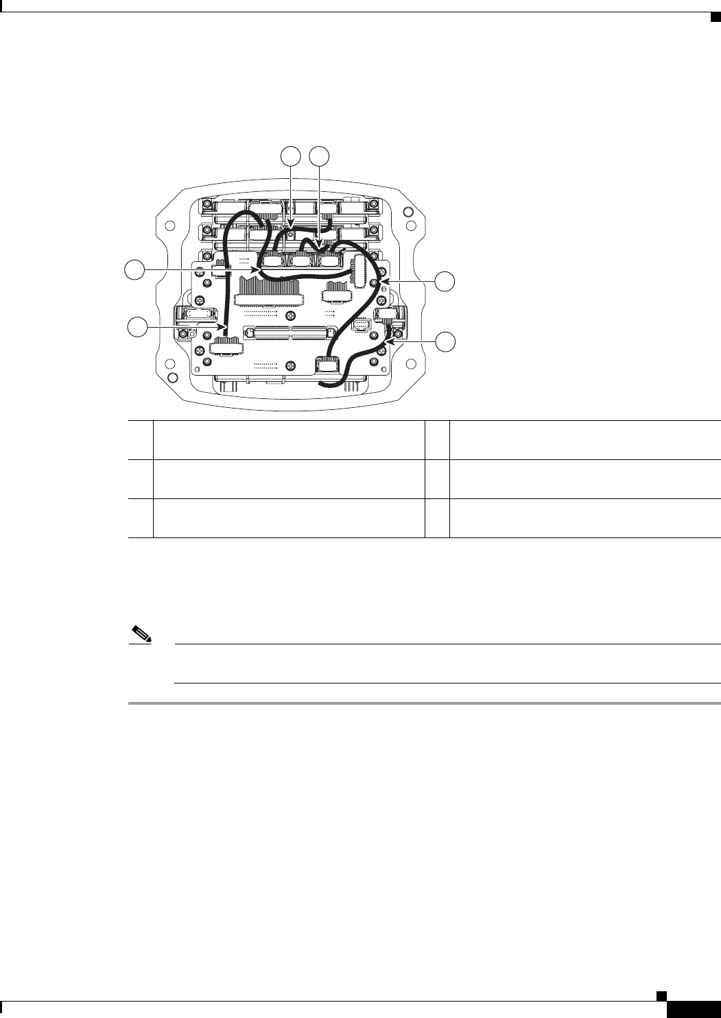
For a 3-WMIC configuration, connect the cables to the wiring card as shown in Figure 3-14.
Figure 3-14 3-WMIC Configuration
Step 5 Connect the 60-pin Serial Mobile Interface Card (SMIC) serial console connector cable to port J13 on
the wiring card.
Step 6 Connect the 20-pin FESMIC LED cable to port J5 on the wiring card.
Note When connecting the serial console and LED ribbon cables, use them to secure the other cables
connecting the card stack to the wiring card.
270478
6
4
5
3
1 2
1 Connect the FESMIC 10-pin FE1X cable to
WMIC 3.
2 Connect the FESMIC 10-pin FE2X cable to
WMIC 2.
3 Connect the FESMIC 10-pin FE3X cable to
WMIC 1.
4 Thread the FE extender cable under the card
stack to the antenna end cap side.
5 Connect the WMIC 2 console port to port J2
on the wiring card, using the 20-pin cable.
6 Connect the WMIC 3 console port to port J3
on the wiring card using a 20-pin cable.


