


14 Replacing the Cisco 3660 Router Backplane
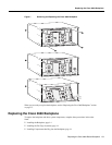
Replacing the Cisco 3660 Backplane
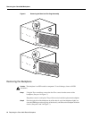
Installing the Backplane
Caution The backplane is an ESD-sensitive component. To avoid damage, observe all ESD
precautions.
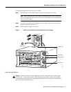
This procedure describes how to replace the backplane:
Step 1 Position the chassis so that the front panel faces you.
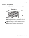
Step 2 Angle the backplane slightly (to clear the EMI fingers on the top edge of the chassis),
pivot the right side of the backplane, and align the backplane in the chassis. (See parts 2
and 3 in Figure 7.)
Note Align the backplane so that the connectors face the rear of the router.
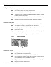
Step 1 Using the Torx screwdriver, secure the backplane to the chassis using the Torx screws
removed earlier in Step 1 of the “Removing the Backplane” section on page 12.
To ensure correct alignment, install the screws in this order (see Figure 7):
1. Upper left corner screw
2. Lower left corner screw
3. Upper and lower right corner screws
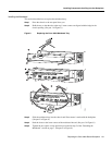
Installing the Fan Cage Assembly
Use the following procedure to replace the fan cage assembly:
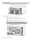
Step 1 Facing the front of the router, align the tabbed edge of the bezel/fan cage assembly with
the chassis tab slots (see part 3 in Figure 6), and push down slightly to engage the tabs
(see part 2 in Figure 6).
Step 2 Swing the bezel/fan cage assembly into the chassis. (See part 1 in Figure 6.)
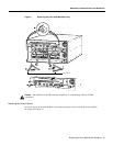
Step 3 Locate the two screw covers on the bezel’s right edge. (See part 1 in Figure 5.)
Step 4 Using the Phillips screwdriver, tighten the two captive screws and close the screw covers.
(See part 2 in Figure 5.)
Installing Components that Plug into the Backplane
This section describes the following procedures:
• Installing the Mainboard, page 15
• Installing Network Modules, page 16
• Installing the Chassis Shield, page 16
• Installing Power Supplies, page 16