


Chapter 1 Module Overview and Specifications
Supervisor Engines
1-8
Catalyst 4500 Series Module Installation Guide
78-13267-06
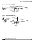
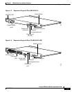
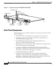
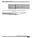
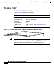
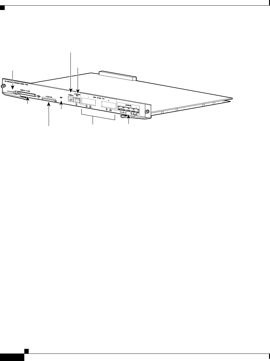
Figure 1-9 Supervisor Engine V-10GE (WS-X4516-10GE)
Front-Panel Components
The following connectors, LEDs, and buttons are located on the front panel of the
supervisor engine:
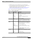
• The STATUS LED, which indicates the operating state of the module
• Two Gigabit uplink ports (WS-X4013, WS-X4013+, WS-X4014, and
WS-X4515 supervisor engines only)
• Four SFP Gigabit uplinks ports and 2 10-Gigabit uplink ports on
WS-X4013+10GE and WS-X4016-10GE.
• Eight unmarked switch load indicator LEDs, which provide an approximation
of the current traffic across the backplane
• A console port (DB-25 for the WS-X4012; RJ-45 for the WS-X4013,
WS-X4013+, WS-X4013+ TS, WS-X4013+10GE, WS-X4014, WS-X4515,
WS-X4516, and WS-X4516-10GE supervisor engines)
• An Ethernet management port (RJ-45)
• A link status LED, which provides status for the management port
(10BASE-T on the WS-X4012 and 10/100BASE-T on the WS-X4013,
WS-X4013+, WS-X4013+ TS, WS-X4013+10GE, WS-X4014, WS-X4515,
WS-X4516, and WS-X4516-10GE supervisor engines)
120474
STATUS LED
RESET
button
10 GE uplink
ports
Gigabit SFP
ports
Switch load
indicators
CONSOLE port
Ethernet
management port
Compact
Flash
port