


1-9
Catalyst 4500 Series Module Installation Guide
78-13267-06
Chapter 1 Module Overview and Specifications
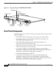
Supervisor Engines
• The Reset button (recessed), which allows you to reset the system
• The CompactFlash port and eject button (WS-X4013+, WS-X4013+ TS,
WS-X4013+10GE, WS-4014, WS-X4515, WS-X4516, and
WS-X4516-10GE supervisor engines only) (refer to Using the Compact
Flash on the Catalyst 4000 Family Supervisor Engine III and IV.)
Table 1-1 describes the supervisor engine LEDs.
Table 1-1 Supervisor Engine LEDs
LED Color/State Description
STATUS Indicates the results of a series of self-tests.
Green All diagnostic tests passed.
Red A test failed.
Orange System boot or diagnostic test is in
progress.
Off Module is disabled.
UTILIZATION Green 1–100% If the switch is operational, this display
indicates the current traffic load over the
backplane (as an approximate percentage).
LINK Indicates the status of the 10/100BASE-T
Ethernet management port or uplink ports.
Green The link is operational.
Orange The link is disabled by user.
Flashing orange The power-on self-test indicates a faulty
port.
Off No signal is detected or there is a link
configuration failure.
ACTIVE Indicates whether the uplink port is active
or not.
Green The port is active.
Off The port is not active.