


3
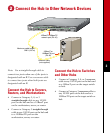
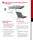
Connect the Hub to Other Network Devices
(continued)
R
A
T
IN
G
1
0
0-12
7
/ 2
0
0
-2
4
0
V
~
2
A
/1A
50
/ 6
0
H
z
CONSOLE
UP
MEDIA MODULE
DOWN
DC INPUT
D
C
IN
P
U
T
S
F
O
R
R
E
M
O
T
E
P
O
W
E
R
S
U
P
P
L
Y
S
P
E
C
I
F
IE
D
IN
M
A
N
U
A
L
+
5
V
@
6
A
,
+
1
2
V
@
1
A
1
0
/1
0
0
B
A
S
E
-
T
X
S
T
A
T
D
U
P
10
0
R
A
T
IN
G
1
0
0
-12
7
/ 2
00
-2
4
0
V
~
2
A
/1
A
5
0
/ 6
0
H
z
CONSOLE
UP
MEDIA MODULE
DOWN
DC INPUT
D
C
IN
P
U
T
S
F
O
R
R
E
M
O
T
E
P
O
W
E
R
S
U
P
P
L
Y
S
P
E
C
IF
IE
D
IN
M
A
N
U
A
L
+
5
V
@
6
A
,
+
1
2
V
@
1
A
1
0
/
1
0
0
B
A
S
E
-
T
X
ST
A
T
D
U
P
10
0
R
A
T
IN
G
1
0
0
-12
7
/ 2
0
0
-2
4
0
V
~
2
A
/1
A
5
0
/ 6
0 H
z
CONSOLE
UP
MEDIA MODULE
DOWN
DC INPUT
D
C
IN
P
U
T
S
F
O
R
R
E
M
O
T
E
P
O
W
E
R
S
U
P
P
L
Y
S
P
E
C
IF
IE
D
IN
M
A
N
U
A
L
+
5
V
@
6
A
,
+
1
2
V
@
1
A
DU
P
LIN
K
1
0
0
B
A
S
E
-
F
X
R
X
TX
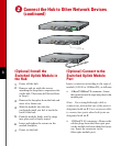
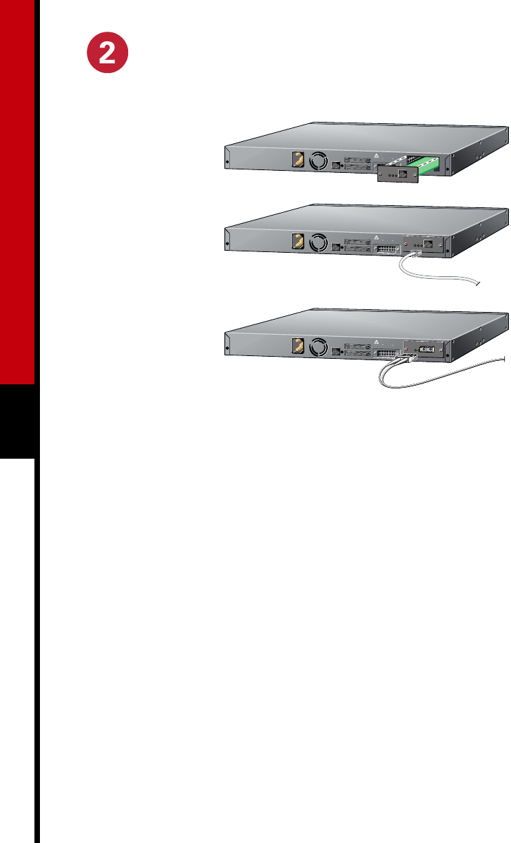
(Optional) Install the
Switched Uplink Module in
the Hub
1
Power off the hub.
2
Remove and set aside the screws
attaching the faceplate to expansion slot
on the hub. The screws will be used later
in Step 6.
3
Remove the faceplate from the hub and
store it for future use.
4
Slide the module into the slot
card-guides until you feel it touch the
back of the hub.
5
Push the module firmly until it snaps
into place and is firmly seated.
6
Insert and tighten the screws on the
module faceplate.
7
Power on the hub.
(Optional) Connect to the
Switched Uplink Module
Port
Insert a connector according to the type of
module (10/100 or 100BaseFX), as follows:
• 10BaseT/100BaseTX connector—Insert
the connector until it snaps into place in the
module port.
Note: Use a straight-through cable to
connect two ports when one of the ports is
designated with an X. Use a crossover cable
to connect two ports when both ports are
designated with an X.
• 100BaseFX SC connector—Remove the
rubber plugs from the fiber-optic port
on the module and store them for future
use. Insert the connector in the
fiber-optic module port.