


Contents
2
Cisco Communication Media Module for Catalyst 6500 Series Switch and Cisco 7600 Series Router Installation and Verification Note
Contents
This publication contains these sections:
• Front Panel Descriptions, page 2
• Requirements, page 6
• Safety Overview, page 7
• Required Tools, page 10
• Installing and Removing the Module, page 10
• Removing and Replacing Port Adapters, page 19
• Verifying the Installation, page 25
• RJ-45 Port Connector and Cabling Specifications, page 25
• RJ-21 Port Connector and Cabling Specifications, page 27
• Accessing the Port Adapter Ports, page 28
• Configuring the Port Adapter Ports, page 29
• Configuring the Port Adapter Clock Source, page 29
• Disaster Recovery for Module Software Upgrades, page 30
• Password Recovery, page 32
• Regulatory Standards Compliance, page 33
• Related Documentation, page 33
• Obtaining Documentation, Obtaining Support, and Security Guidelines, page 33
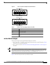
Front Panel Descriptions
These sections describe the front panel features of the module and the port adapters:
• CMM Module, page 2
• 6-Port T1 and E1 Port Adapters, page 4
• 24-Port FXS Port Adapter, page 5
• Ad-Hoc Conferencing and Transcoding Port Adapter, page 6
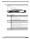
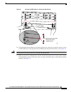
CMM Module
The front panel features of the modules are as follows:
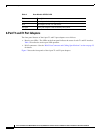
• STATUS LED—When the module powers up, it initializes various hardware components and
communicates with the supervisor engine. The STATUS LED shows the dialog with the supervisor
engine and the results of the initialization. During the normal initialization sequence, the STATUS
LED changes from off to red, to orange, and then to green. Table 1 describes the STATUS LED
operation.
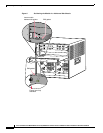
• Port adapter slots—Figure 1 and Figure 2 show the E1 port adapter in the left and middle slots, with
a blank filler plate in the right slot.
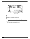
• REAR MODULE STATUS LED—Table 2 describes the REAR MODULE STATUS LED operation.