


Verifying the Installation
25
Cisco Communication Media Module for Catalyst 6500 Series Switch and Cisco 7600 Series Router Installation and Verification Note
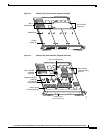
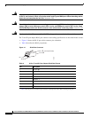
Caution Using the screws or standoffs to seat the port adapter could warp the port adapter. Before you install and
tighten the securing screws, ensure that the port adapter is fully seated by visually verifying that the
bottom of the port adapter is in contact with the top of the mounting posts.
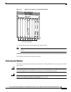
Step 6 Install the two standoffs and two Phillips screws to secure the port adapter. (See Figure 12.)
Step 7 Install the module into the Catalyst 6500 series switch or Cisco 7600 series router; see the “Installing
the Module” section on page 10.
Verifying the Installation
Enter the show module mod-num command to verify that the system acknowledges the new module and
has brought it online.
This example shows the output of the show module command with a module in slot 4:
Console> (enable) show module 4
Mod Slot Ports Module-Type Model Sub Status
--- ---- ----- ------------------------- ------------------- --- --------
4 4 5 Communication Media Mod. WS-SVC-CMM no ok
Mod Module-Name Serial-Num
--- -------------------- -----------
4 sad054206jc
Mod MAC-Address(es) Hw Fw Sw
--- -------------------------------------- ------ ---------- -----------------
4 00-01-64-46-6a-0e to 00-01-64-46-6a-17 1.0 12.2(2002012.2(20020530:100440
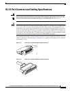
RJ-45 Port Connector and Cabling Specifications
Warning
Before opening the unit, disconnect the telephone-network cables to avoid contact with
telephone-network voltages.
Statement 1041
Warning
Do not work on the system or connect or disconnect cables during periods of lightning activity.
Statement 1001
Warning
Never install telephone jacks in wet locations unless the jack is specifically designed for
wet locations.
Statement 1036
Warning
Never touch uninsulated telephone wires or terminals unless the telephone line has been
disconnected at the network interface.
Statement 1037