


10
Catalyst 4500-X AC-Input Power Supply Installation Note
OL-26535-01
Installing the Power Supply
Note The chassis determines which airflow direction is correct by polling all of the fan assemblies and
the power supplies. The airflow direction for all of the devices must be the same. If the airflow
direction of the replacement power supply or the redundant power supply does not match the fan
assemblies airflow direction, the system software shuts down the power supply and generates a
power supply mismatch error message on the console.
Step 3 If the chassis power supply bay is empty, proceed to Step 4. If you are replacing a power supply already
installed in the chassis power supply bay, go to the “Removing the Power Supply” section on page 11.
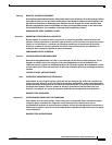
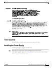
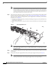
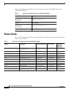
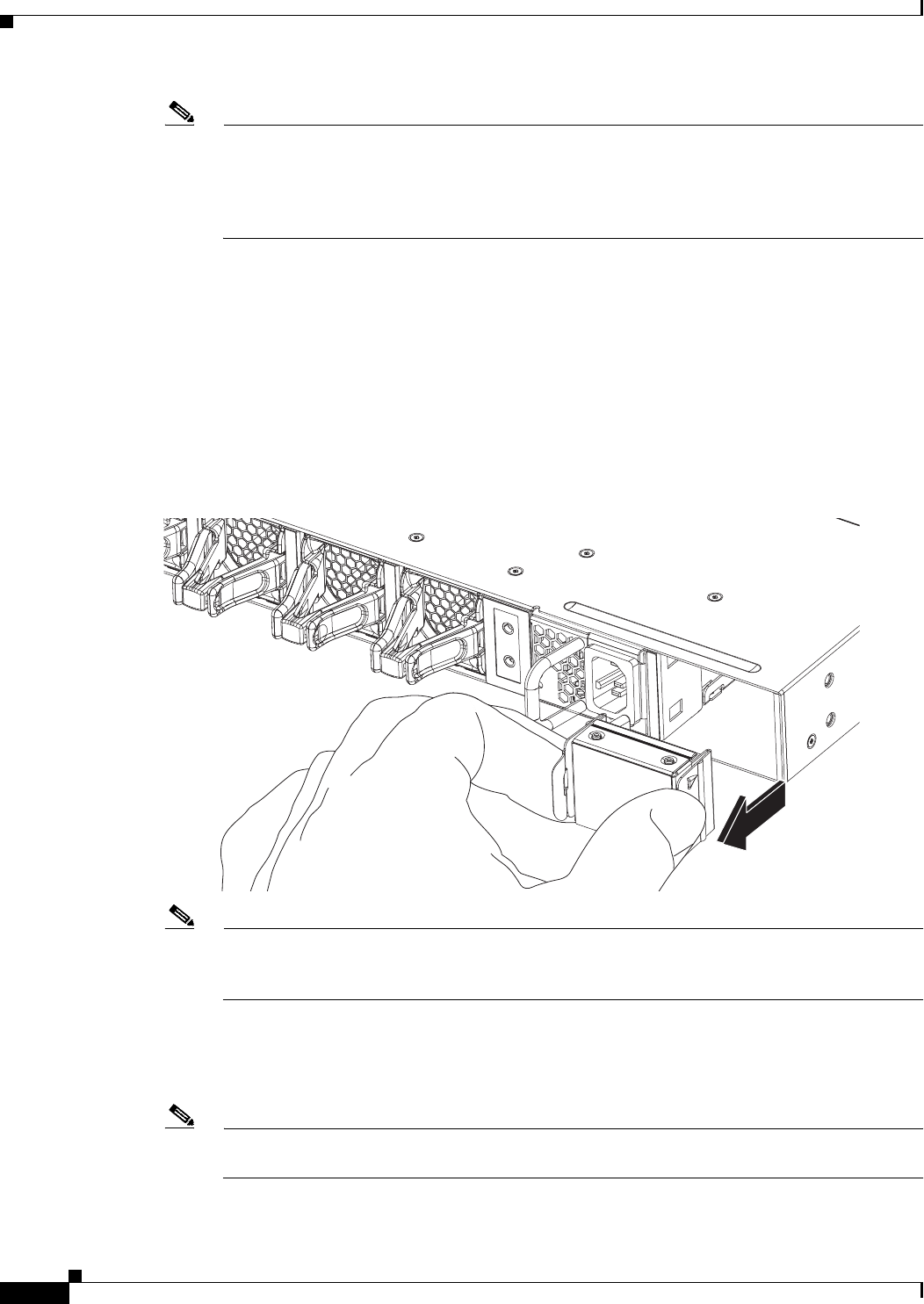
If the chassis power supply bay is empty, but has a power supply blank cover installed, you must remove
the blank cover (see Figure 2):
a. Grasp the two retaining clips with your thumb and forefinger and squeeze to release the blank cover
from the power supply bay.
b. While still squeezing the two clips, pull on them to remove the blank cover from the power supply
bay.
Figure 2 Power Supply Blank Cover
Note If the redundant power supply bay on the Catalyst 4500-X chassis is unused, you must cover it
with a power supply blank cover (part no. C4KX-PWR-BLANK=) to maintain proper airflow
through the chassis.
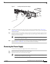
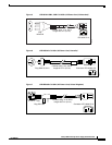
Step 4 Using two hands to support the new power supply, position it in front of the power supply bay and slide
it into the bay.
Step 5 Firmly push on the power supply handle to fully seat the power supply in the bay. (See Figure 3.)
Note The retaining clip will pivot in and then snap into place when the power supply is fully installed
in the bay. You can hear a click as the power supply release lever snaps into place.
332207