


1
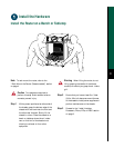
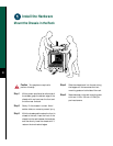
Install the Hardware
EJECT
SLOT 0
SLOT 1
NORMAL
CPU HALT
RESET
AUX.
CONSOLE
ROUTE SWITCH PROCESSOR 2
SLAVE
MASTER
SLAVE/MASTER
ENABLE
ENABLE
EJECT
SLOT 0
SLOT 1
NORMAL
CPU HALT
RESET
AUX.
CONSOLE
ROUTE SWITCH PROCESSOR 2
SLAVE
MASTER
SLAVE/MASTER
0
I
AC
OK
FAN
OK
OUTPUT
FAIL
0
I
AC
OK
FAN
OK
OUTPUT
FAIL
POWER
A
POWER
B
53385
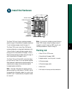
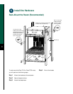
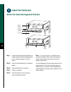
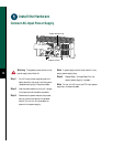
Blower module
Cable-management
bracket
Card cage and
processor
modules
Air intake vent
Power supplies
Chassis
grounding
receptacles
Interface
processor slot
numbering
scheme
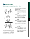
The Cisco 7513 has 13 slots: interface processor
slots 0 through 5, Route Switch Processor slots 6 and
7, and interface processor slots 8 through 12.
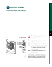
The Cisco 7576 router is two Cisco 7500 series
routers configured on a single split backplane, with
13 slots. Router A uses interface processor slots 0
through 5 with a Route Switch Processor in slot 6.
Router B uses interface processor slots 8 through 12
with a Route Switch Processor in slot 7.
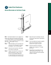
The Cisco 7513 and Cisco 7576 routers have bays
for up to two AC-input or DC-input power supplies.
Each chassis will operate with one power supply, but
a second power supply allows load sharing and
increased system availability.
Note The Cisco 7576 does not support the high
system availability (HSA) feature. The RSP in slot 6
is automatically the system master for router A and
the RSP in slot 7 is automatically the system master
for router B.
Note If you are only configuring one of the two
Cisco 7576 internal routers, configure router A
instead of router B. Install an RSP in slot 6, and
interface processors in slots 0 through 5.
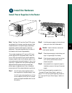
Packing List
• 1 Cisco 7513 or 7576 router
• 1 Route Switch Processor (RSP)
• Y-adapter cables, 1 auxiliary and 1 console
• 1 AC power supply
• 1 AC power supply cable
• 1 Power cord
• 1 Anti-static wrist strap and documentation