


2-93
Cisco ASR 9000 Series Aggregation Services Router Hardware Installation Guide
Chapter 2 Unpacking and Installing the Chassis
Installing Chassis Accessories
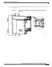
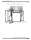
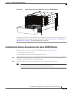
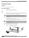
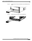
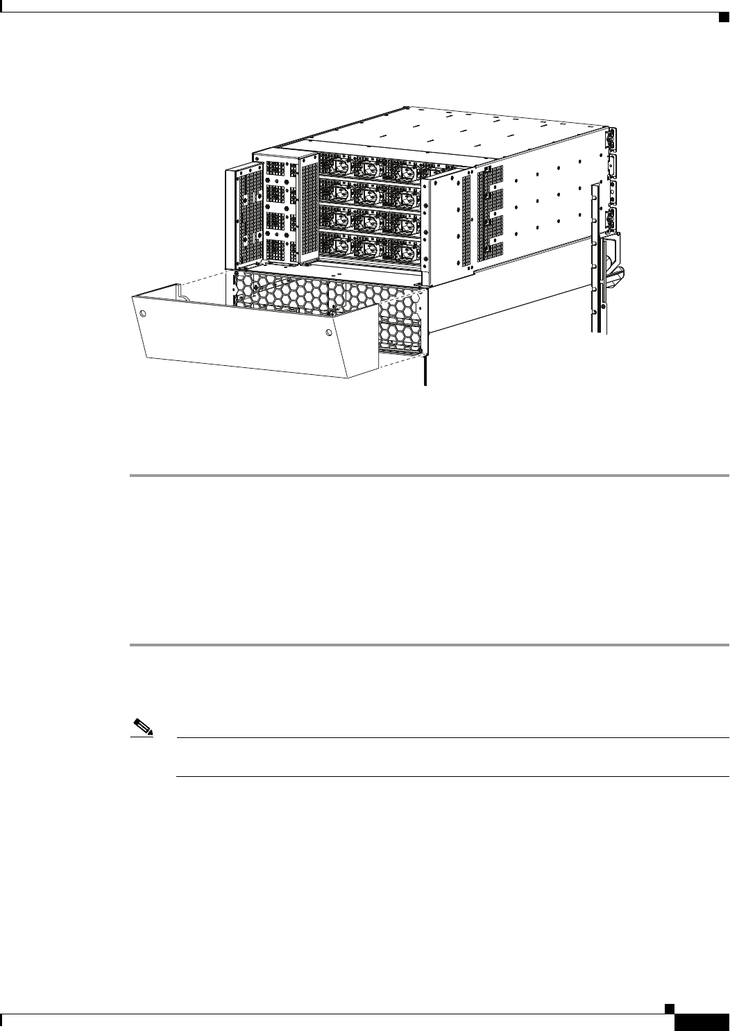
Figure 2-84 Optional Rear Exhaust Air Deflector on the Cisco ASR 9922 Router
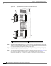
After the chassis has been installed in the rack and all chassis accessories have been attached, you can
install the fan trays, power supply modules, RP cards, FCs and LCs. See Chapter 3, “Installing Cards
and Modules in the Chassis,” for detailed installation instructions.
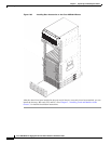
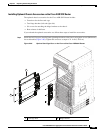
Installing Base Chassis Accessories on the Cisco ASR 9912 Router
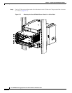
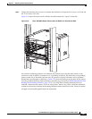
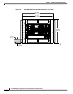
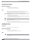
The base chassis accessories for the Cisco ASR 9912 Router include (Figure 2-85):
• One honeycomb cosmetic cover
• One vented bezel to cover the front of the power system
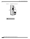
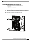
Step 1 Attach the honeycomb cosmetic cover to the front of the chassis above the cable management bracket by
aligning the cover above the screw tabs on the chassis.
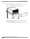
Step 2 Attach the vented bezel cover by snapping it into place in front of the power system.
Note You will need to remove the vented bezel cover in order to install the power system. After the
power system is installed, you can re-install the vented bezel cover.
303591