


3-11
Cisco AS5800 Universal Access Server Dial Shelf Card Guide
78-7097-03
Chapter 3 Channelized T3 Trunk Card
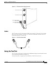
Using the Test Port
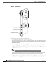
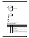
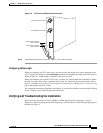
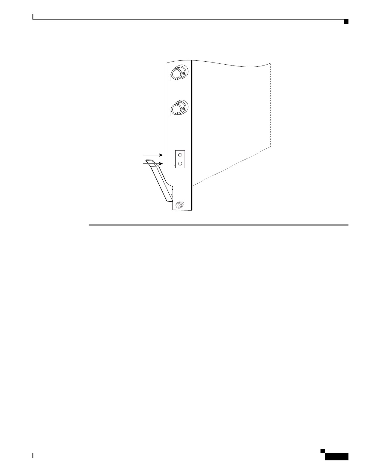
Figure 3-6 CT3 Trunk Card BNC Cable Connections
Step 2 Attach the network end of your CT3 cable to your external network.
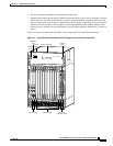
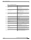
Configuring Cable Length
When you configure your CT3 trunk cards, you must include the length of the cable connected to the
card. To specify this length, use the cablelength command and designate the length of the DS3 cable, as
shown in Table 3-3. Cable length is a number of feet from 0 to 450.
When you configure your system for CT3 lines, you must also include additional commands to define
framing, line code, clock source, signaling, and so forth. For additional software information, refer to
the Cisco AS5800 Universal Access Server Operation, Administration, Maintenance, and Provisioning
Guide that shipped with your system.
This completes the trunk card installation procedure. To verify the installation, proceed to the following
section “Verifying and Troubleshooting the Installation.”
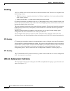
Verifying and Troubleshooting the Installation
When you first power ON your Cisco AS5800, all LEDs light while the system runs a series of
diagnostics. After the system passes initial diagnostics, all LEDs shut off. The LEDs then light again as
described in Table 3-1.
CHANNELIZED T3
RCVR
XMTR
TX (OUT)
RX (IN)
12241
Receive BNC connector
Transmit BNC connector
Transmit DSx1 bantam
jack connector
Receive DSx1 bantam
jack connector