


Cisco 7000 and Cisco 7507 Chassis Replacement Instructions 21
Moving System Components
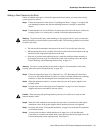
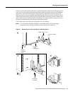
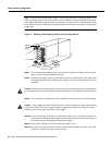
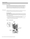
Step 6 While keeping the carrier at a 90-degree orientation to the backplane, carefully slide the
carrier into the slot untilthe back of the faceplate makes contact with the ejectorlevers. (See
Figure 8b.)
Step 7 Using the thumb and forefinger of each hand, simultaneously push the top lever down and
the bottom lever up 90 degrees to fully seat the board connectors in the backplane. (See
Figure 8c.)
Caution Do not use unnecessary force when installing processor modules. Always guide the board
carrier into the slot only until the carrier faceplate is flush against the ejector lever, then use the
ejector levers to push the interface processor fully into the slot and seat it in the backplane properly.
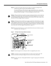
Step 8 Use a screwdriver (Number 2 Phillips or 1/4-inch flat-blade) to tighten the captive
installation screws on the top and bottom of the faceplate. (See Figure 8).
Step 9 Repeat Steps 1 through 8 for each remaining processor module, working from right to left.
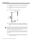
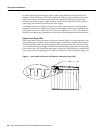
Before removing a processor module from the existing chassis, remove the blank board
carrier from the corresponding slot in the replacement chassis. Try to replace interface
processors in the same slot number you removed them from to avoid confusion when
reconnecting cables and checking the installation.
Step 10 Proceed to the next section to move the power supplies.
Note Leave the blank board carriers installed in all unfilled interface processor slots.
Moving Power Supplies
You can insert the power supplies and connect the power cables, but do not turn on system power
until you are ready to restart the system and check the installation. Always install the first power
supply in the lower power supply bay and the second, if any, in the upper bay. Remember to tighten
the captive installation screw on the top of each power supply. The screw prevents the supply from
becoming dislodged from the power connections inside the chassis and also provides proper
grounding for the system.
Follow these steps to move a power supply:
Step 1 If you have already removed all power supplies, proceed to Step 7.
Step 2 Ensure that the switch on each power supply is turned fully to OFF (O), then disconnect
all power cords from the power sources.
Step 3 Disconnect the power cable from each power source.
Step 4 Disconnect the power cable from each power supply.
Step 5 Use a screwdriver to loosen the captive installation screw on the power supply in the lower
bay.
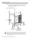
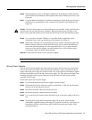
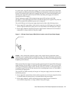
Step 6 Grasp the power supply handle and pull the supply out of the bay. Place one hand
underneath to support the bottom of the supply as you pull it out of the bay. (See Figure 10.)
Immediately proceed to the following step to install the removed power supply in the
replacement chassis.