


Cisco 7000 and Cisco 7507 Chassis Replacement Instructions 3
Product Overview
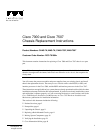
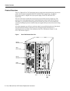
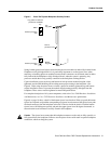
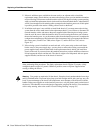
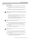
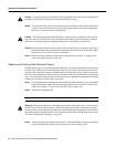
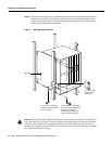
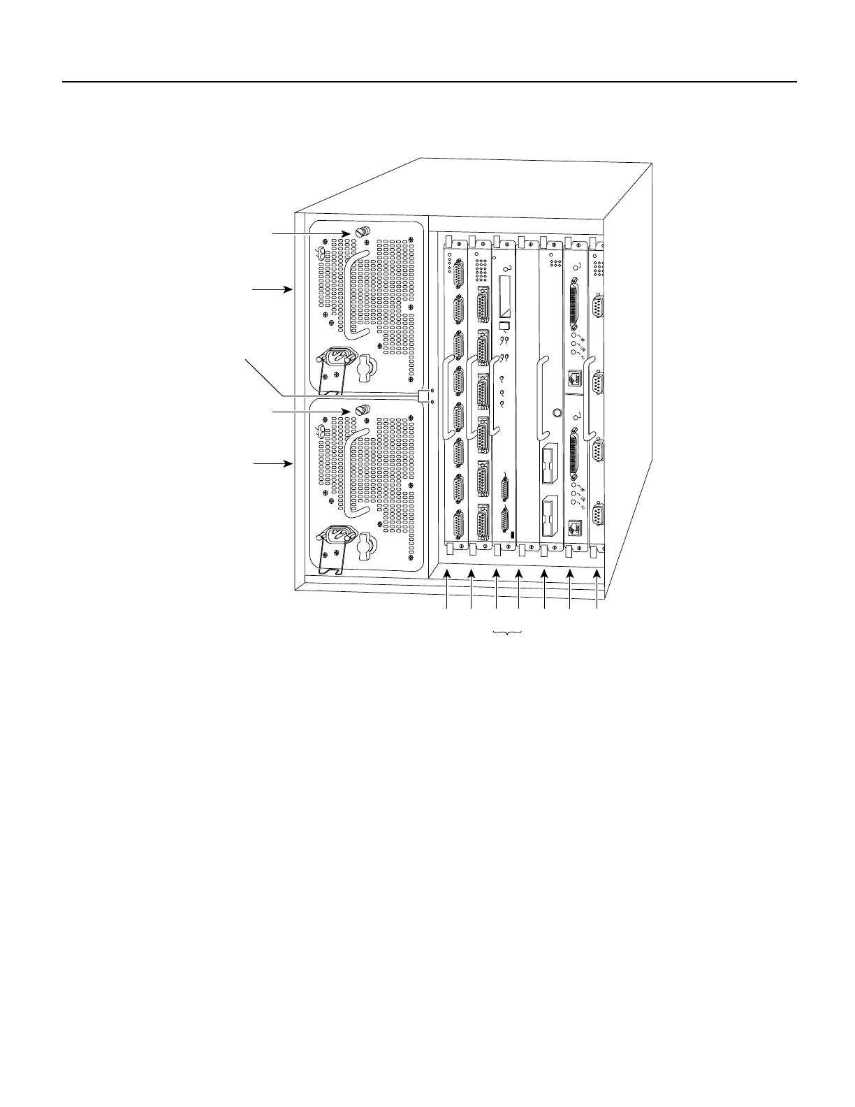
Figure 2 Cisco 7507 Chassis Rear View
The lower power supply bay is the default bay for systems with a single supply. The upper bay
houses the second power supply in systems with redundant power. Power supplies slide into the bays
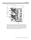
and must be fully inserted before the power switch can be turned on. On each power supply, the
on/off switch prevents the power supply from being removed from the chassis when the power
supply switch (labeled O for the off position, and | for the on position) is in the on (|) position. (See
Figure 3.) When the switch is on, a metal tab extends into a slot in the chassis. When the switch is
turned off (O), the tab is raised and clears the slot. A captive installation screw at the top of each
supply secures the supply in the bay and provides grounding for the system.
ENABLE
ENABLE
EJECT
SLOT 0
SLOT 1
NORMAL
CPU HALT
RESET
AUX.
CONSOLE
ROUTE SWITCH PROCESSOR 2
SLAVE
MASTER
SLAVE/MASTER
H3888
Slot 0
1
2
34 5 6
U
pper
ower supply
C
hassis
g
rounding
e
ceptacles
L
ower
ower supply
I
O
DC FAIL
AC POWER
I
O
DC FAIL
AC POWER
RSP slots
C
aptive
n
stallation screw
C
aptive
n
stallation screw