


9
Cisco 10000 ESR Blower Module Installation
78-10834-01
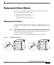
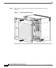
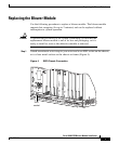
Replacing the Blower Module
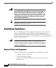
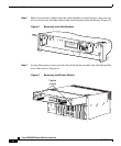
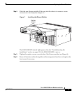
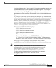
Step 4 Slide the new blower module all the way into the chassis to ensure a secure
connection to the backplane (Figure 7).
Figure 7 Installing the Blower Module
The FANS OK LED should light (green). See the “Troubleshooting the
Installation” section on page 10 if the FANS OK LED is not on.
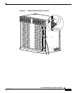
Step 5 Tighten the captive screws on each side of the blower module (see Figure 6).
Step 6 Rerun all interface cables through the cable management brackets and replace the
front cover if necessary.
32225
1
3
2
4
0A
P
R
O
C
E
S
S
O
R
O
N
LY
0B
5
6
7
8
F
A
IL
C
1
0
000
1
G
E
F
A
IL
C
10
00
0
C
h
C
O
12
F
A
IL
C
10
0
0
0
6
C
T
3
F
A
IL
C
1
0
0
00
6
C
T
3
C
100
0
0
P
R
E
C
10
0
00
P
R
E
C
O
N
C
IS
C
O
10
000
C
A
R
R
IE
R
A
L
A
R
M
L
O
O
P
FA
IL
0
2
1
C
IS
C
O
1
0
000
FA
IL
C
O
N
S
O
L
E
E
T
H
E
R
N
E
T
L
I
N
K
A
C
T
I
V
I
T
Y
A
U
X
S
LO
T 0
SLO
T
1
C
IS
C
O
100
00
C
A
R
R
IE
R
A
L
A
R
M
L
O
O
P
F
AIL
0
2
1
100
00
C
A
R
R
IE
R
A
L
A
R
M
L
O
O
P
FAIL
0
2
1
C
A
R
R
IE
R
A
L
A
R
M
L
O
O
P
0
2
1
C
A
R
R
IE
R
A
L
A
R
M
L
O
O
P
0
2
1
FANS
OK
FAN
FAILURE
MULTI-
FAN
FAILURE
When hot swapping this fan tray,
removal and replacement must
be done in under two minutes or
system shutdown will occur.
CAUTION
Captive
screws