


16 Cisco 7000 and Cisco 7507 Rack-Mount Kit Installation Instructions
Installation
Installation
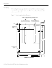
The following sections describe the procedures for mounting the chassis in a 19-inch equipment rack
with two or four mounting posts. Before proceeding, review the guidelines and recommendations in
the section “Prerequisites” on page 7 to protect your safety, to maintain sufficient clearance around
the rack during and after the installation, and to ensure proper airflow through the chassis after the
installation.
Warning To avoid potentially serious bodily injury, this procedure requires two or more people to
perform.
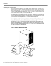
Some equipment racks provide a power strip along the length of one of the rear mounting strips. If
your rack has this feature, we recommend that you fasten the brackets and install the interface
processor end of the chassis at the opposite side of the rack.
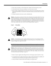
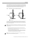
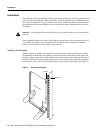
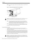
Installing the Brackets
The two brackets are identical. The inner side of each bracket has a ledge at the bottom to support
the undersides of the chassis, and shielding to provide electrical isolation between the chassis and
the rack. A flange on the front of each bracket provides five mounting holes at the top, and three at
the bottom. Mount the bracket with the flange in front of the rack post, and with the inner (shielded)
side facing the center of the rack. The ledge should be at the bottom of the bracket. (See Figure 9.)
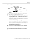
Figure 9 Positioning a Bracket
H2288
Rack post
Flange
Shielded side