


Cisco 7000 and Cisco 7507 Rack-Mount Kit Installation Instructions 17
Installation
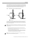
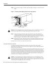
After you install both brackets in the rack, you must connect the spanner bar on each bracket to the
opposite bracket. The spanner bars are required to prevent both ends of the brackets (at the front and
rear of the rack) from separating or drifting apart. The cutouts in the brackets are to accommodate
the ear brackets that attach to the chassis to the rack. (Refer to Figure 2 on page 4.)
To install the brackets in the rack, you will secure each bracket to a rack post with three
10-32 x 5/8-inch Phillips, pan-head screws. If possible (if the holes line up), use the top-most and
bottom most mounting holes in the bracket. Always use the bottom mounting hole on the bracket. If
the top mounting hole does not line up with a hole in the rack post, use one of the other two holes
near the top of the bracket.
Mounting the Brackets to the Rack Posts
Follow these steps to mount each bracket to a rack post:
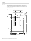
Step 1 Measure the space between the inner edges of the left front and right front equipment
rack-mounting posts toensure that it is at least 17.72 inches. The chassis is 17.5 inches wide
and must fit between the mounting posts.
Step 2 Measure the distance between the holes in the mounting posts to ensure that it is
18.31 inches ( .063 inches). Make several measurements down the length of the posts to
ensure they are parallel.
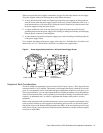
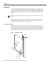
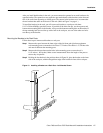
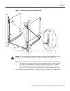
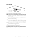
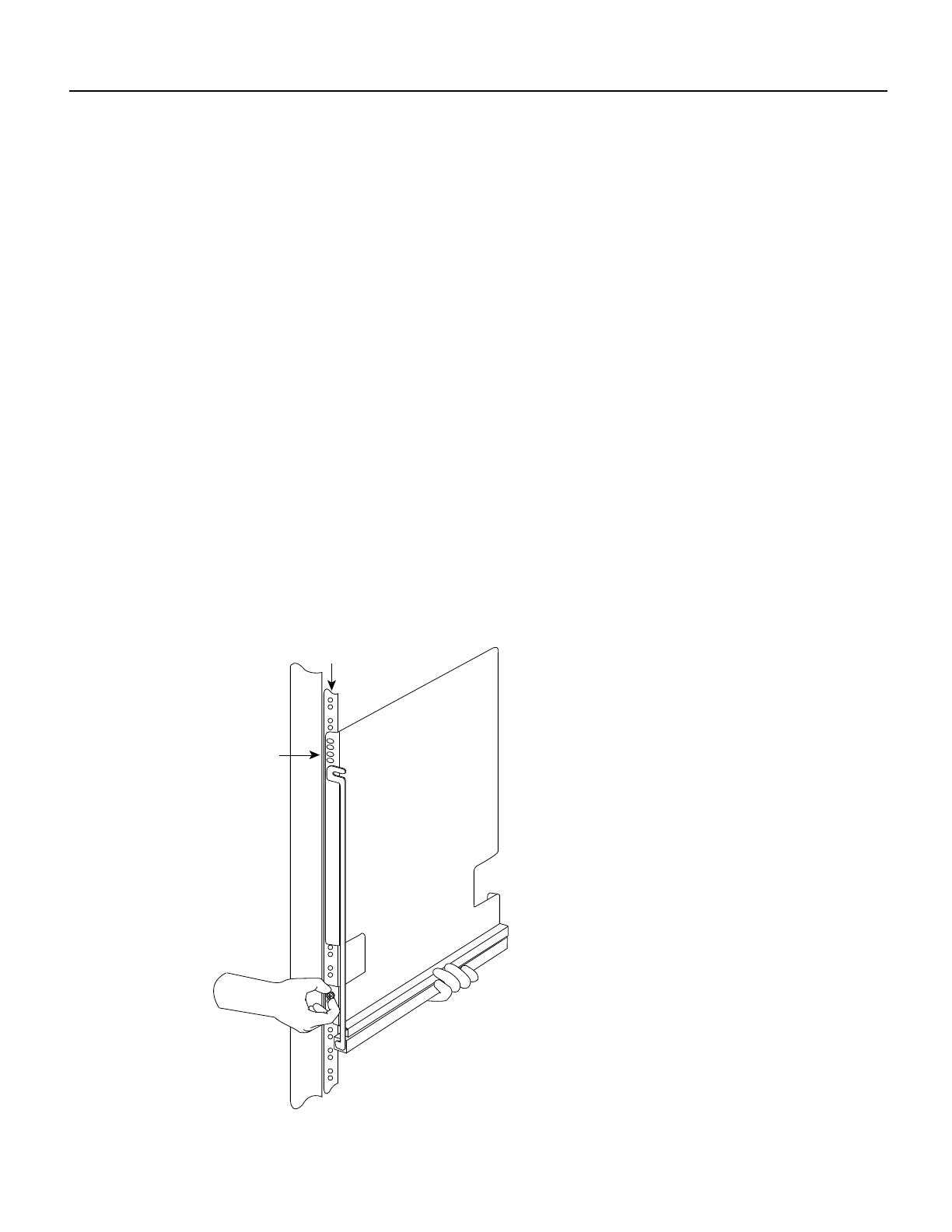
Step 3 Holding the first bracket in the position shown in Figure 10, place the bracket on the inner
side of the rack post, with the flanged front edge of the bracket in front of the rack post.
Figure 10 Installing a Bracket on a Rack Post—Left Bracket Shown
H2289
Rack post
Flange
Shielded side