


10 Cisco 7010 and Cisco 7505 Chassis Replacement Instructions
Replacing the Chassis
Removing the Existing Chassis from the Rack
Before removing the existing chassis from the rack, you must shut down the system power and
disconnect the power cord and all interface cables. To help avoid problems when you install the new
chassis, label all interface cables with their slot/port address and mark the positions of the chassis
ears (with tape, chalk, or a marker) so that you can install the new chassis in the same position.
Two chassis ears support the chassis in the rack. The ears are secured to the chassis sides and to the
rack posts, so that the chassis is cantilevered off the ears. We recommend that two people perform
this procedure: one person to support the chassis while the other person removes the screws that
secure the ears to the rack.
Follow these steps to remove the existing chassis from the rack:
Step 1 Turn off the system power and disconnect the power cord and all interface cables from the
chassis.
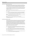
Step 2 Have a second person support the chassis while you perform this step. From the front of
the rack, use a 1/4-inch flat-blade screwdriver to loosen and remove each of the eight
10-32 x 3/8-inch, slotted screws (four on each side) that secure the chassis ears to the rack.
Step 3 Pull the chassis out of the rack and place it on the floor or a table.
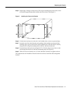
Step 4 Use a number 2 Phillips screwdriver to loosen and remove the two M4 x 10-mm, Phillips
flathead screws that secure the ears to the chassis sides.
Step 5 Pull the ears off the chassis, and place the ears and all fasteners aside.
This completes the chassis removal procedure. If you have not yet installed the new chassis in the
rack, proceed to the next section.
Installing the New Chassis in the Rack
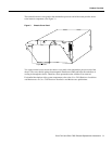
Mount the chassis in the rack before connecting any interface or power cables. If possible, install the
new, empty chassis in the rack first, then install the system components from the old chassis. The
chassis is supported in the rack by two chassis ears, which attach to the sides of the chassis and to
the mounting strips on the rack. Each chassis ear has two studs that fit into holes in either the
interface processor end or the noninterface processor end of the chassis, whichever will be in the
front of the rack. To mount the chassis, install the ears on the chassis first, then secure the ears to the
rack mounting posts or strips. We recommend that two people perform this procedure: one person
to support the chassis in the rack while the other person secures the ears to the rack. Before lifting
the chassis, ensure that your path to the rack is unobstructed.
Follow these steps to install the new chassis in the rack:
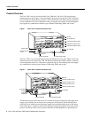
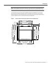
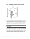
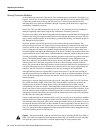
Step 1 Position the chassis so that the end that will be in the front of the rack is closest to you.
Figure 5 shows the correct orientation if the noninterface processor end of the chassis will
be installed at the front of the rack.
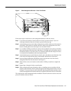
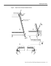
Step 2 Attach the right chassis ear to the chassis first. Hold the ear in the orientation shown in
Figure 5, with the studs pointing toward the chassis and the mounting strip facing you.
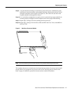
Step 3 Insert the two studs through the holes on the side of the chassis. The ear should be flush
against the chassis side.
Step 4 Insert two M4 x 10-mm, Phillips flathead screws through the ears and into the chassis sides.
Use a number 2 Phillips screwdriver to tighten the screws.