


Cisco 7010 and Cisco 7505 Chassis Replacement Instructions 17
Replacing the Chassis
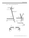
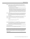
Step 9 Using the thumb and forefinger of each hand to pinch each ejector, simultaneously push
both ejectors inward (toward the carrier handle) until they snap into place and are at a full
90-degree orientation to the faceplate. (See Figure 8c.) The carrier ears (the ends of the
faceplate) should be flush against the chassis.
Step 10 Use a screwdriver to tighten the two captive screws to prevent the processor module from
becoming partially dislodged from the backplane and to ensure proper EMI shielding.
Step 11 Repeat Steps 2 through 10 for the remaining interface processors.
Step 12 Repeat Steps 3 through 10 for the SP (or SSP) and RP in the Cisco 7010, and the RSP1 in
the Cisco 7505.
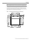
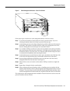
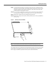
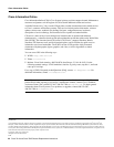
Figure 9 Handling a Processor Module
Note Leave the interface processor filler installed in any unfilled interface processor slots.
This completes the processor module removal and replacement procedure. If you now need to install
the new chassis in an equipment rack, proceed to the section “Installing the New Chassis in the
Rack” on page 10. Otherwise, proceed to the next section to check the installation.
H1985
Captive installation
screws