


Cisco 7000 and Cisco 7507 Rack-Mount Kit Installation Instructions 25
Installation
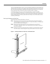
Replacing Power Supplies and Interface Cables
Before proceeding, ensure that you have sufficient working space (at least three feet) behind the
chassis, and that access to the power supply bays is not blocked by an equipment rack power strip or
cables from other equipment. If cables from other equipment are in the way, move them aside and
temporarily secure them with tie wraps before proceeding. Remember that cables that block access
to the bays or processor slots might also block status LEDs from view and impede the flow of
cooling air through the chassis.
Always install the first power supply in the lower power supply bay and the second, if any, in the
upper bay.
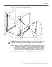
Follow these steps to replace the power supplies:
Step 1 Place the power switch in the OFF (O) position. The interlock tab should not extend out of
the unit.
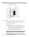
Step 2 Hold the power supply by the handle and place your other hand underneath to support the
bottom.(See Figure 13 on page 22.)
Step 3 Align the power supply so that it will go straight into the slot.
Step 4 Push the power supply all the way into the bay. Do not use unnecessary force; firmly push
the supply back into the bay until the power supply front panel is flush with the chassis rear
panel.
Caution When inserting a power supply into the bay, do not use unnecessary force. Slamming the
power supply into the bay can damage the connectors on the rear of the supply and inside the chassis.
Step 5 Tighten the captive installation screw on the top of the power supply.
Caution To prevent damage to the chassis components, do not turn on any power supplies until you
are ready to power up the system. The interlock switch that locks the power supply in the slot also
turns ON the system power.
Step 6 If you have AC-input power supplies, plug each power cord into an AC receptacle, then
push each cable retention clip up until it snaps into place around the cable connector. If you
have DC-input power supplies, correctly attach the power cable leads and use the nylon
cable tie for strain relief. Refer to the documentation that accompanied the DC-input power
supplies.
Step 7 Repeat Steps 2 through 6 for the second power supply, if any.
Step 8 Connect each power supply cord to a separate input line.
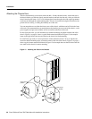
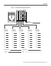
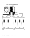
Step 9 Reconnect all interface cables to the ports on the rear of the chassis. Use the configuration
worksheet (if you recorded the cable positions when you disconnected them) to avoid
crossing cables. (For the Cisco 7000, see Figure 16 on page 27, and for the Cisco 7507, see
Figure 17 on page 28.)