


Cisco 7513, Cisco 7513-MX, and Cisco 7576 Card Cage and Backplane Assembly Replacement Instructions 13
Removing Power Supplies
Step 2 Disconnect the power supply cables from the power supplies.
• For DC-input power supplies, refer to the configuration note 1200-Watt DC-Input
Power Supply Replacement Instructions (Publication Number 78-1899-xx) that
shipped with your Cisco 7513, Cisco 7513-MX, or Cisco 7576 chassis equipped with
DC-input power supplies.
• For AC-input power supplies, refer to the configuration note 1200-Watt AC-Input
Power Supply Replacement Instructions (Publication Number 78-1900-xx) that
shipped with your Cisco 7513, Cisco 7513-MX, or Cisco 7576 chassis equipped with
AC-input power supplies.
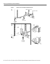
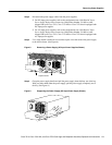
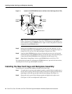
Step 3 Use a large slotted screwdriver to loosen the captive screw that secures the power supply
to the chassis frame. (See Figure 8.)
Figure 8 Removing a Power Supply (AC-Input Power Supplies Shown)
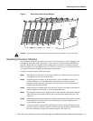
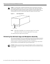
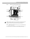
Step 4 Grasp the power supply handle and pull the power supply about halfway out of the bay.
With your other hand under the power supply, pull the power supply completely out of
the bay. (See Figure 9.)
Figure 9 Supporting the Power Supply (AC-Input Power Supply Shown)
H3117
0
I
OK
OK
FAIL
AC
FAN
OUTPUT
0
I
OK
OK
FAIL
AC
FAN
OUTPUT
POWER
B
POWER
A
Captive screws
H3029
0
I
OK
OK
FAIL
AC
FAN
OUTPUT