


16 Cisco 7513, Cisco 7513-MX, and Cisco 7576 Card Cage and Backplane Assembly Replacement Instructions
Exchanging the EEPROM Devices
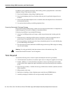
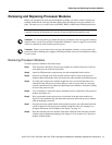
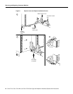
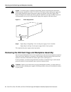
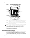
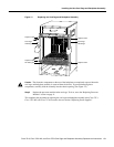
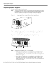
Figure 11 Removing the Card Cage and Backplane Assembly
Step 6
With the captive screws loosened, carefully pull the card cage and backplane assembly
straight out of the chassis until the entire assembly is clear of the chassis sides. (See
Figure 11.) The assembly is not heavy but might be awkward to handle.
Step 7 When the card cage and backplane assembly is completely free of the chassis, carefully
place it on an antistatic mat or foam.
Caution The electronic components on the rear of the backplane are completely exposed when the
card cage and backplane assembly is removed from the chassis. To prevent damaging these
components, place the card cage and backplane assembly on an antistatic mat or foam, and place the
assembly in the same orientation as when it is mounted in the chassis. (See Figure 11.)
This completes the procedure for removing the old card cage and backplane assembly; proceed to
the next section, “Exchanging the EEPROM Devices.”
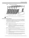
Exchanging the EEPROM Devices
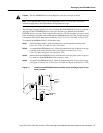
Before you install your new card cage, you must exchange the new EEPROM device(s) on the rear
of the new card cage for 00the old EEPROM device(s) on the rear of your old card cage. The
Cisco 7513 and Cisco 7513-MX include one EEPROM device and the Cisco 7576 includes two
EEPROM devices, one for router A and one for router B. The EEPROM device(s) on your old card
cage have MAC addresses programmed into them, which are necessary for your system to function
properly, and these old EEPROM device(s) are required for your system.
H3096
POWER
A
POWER
B
Captive screw
Captive screw
Captive screw
Captive screw
Card cage
side flange
Air intake grill
Card cage
side flange