


Fast Ethernet Interface Processor (FEIP) Installation and Configuration 29
Selecting Interface Processor Slot, Interface, and Interface Port Numbers
Selecting Interface Processor Slot, Interface, and Interface Port Numbers
This section describes how to identify interface processor slot, interface, and interface port numbers.
Although the interface processor slots in the Cisco 7000, Cisco 7507, and Cisco 7513 are vertically
oriented and those in the Cisco 7010 and Cisco 7505 are horizontally oriented, all models use the
same method for slot and port numbering.
In the router, physical port addresses specify the actual physical location of each interface port on
the router interface processor end. (See the example of an FEIP-2TX shown in Figure 23.) This
address is composed of a three-part number in the format interface processor slot number/adapter
number/interface port number.
• The first number identifies the chassis interface processor slot in which the FEIP is installed (as
shown in the example system in Figure 23).
• The second number identifies the physical interface on the FEIP and is slot 0 (on the left) and slot
1 (on the right).
• The third number identifies the interface port, which is always numbered as interface 0.
Interface ports on the FEIP maintain the same address regardless of whether other interface
processors are installed or removed. However, when you move an FEIP to a different slot, the first
number in the address changes to reflect the new interface processor slot number.
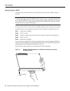
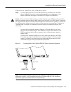
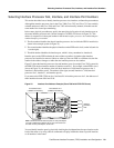
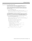
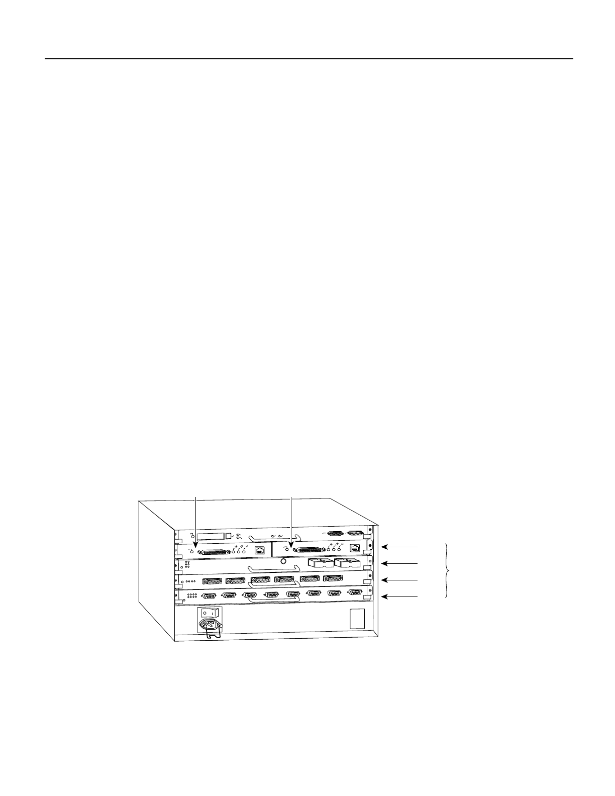
Figure 23 shows the interface processor slots and interface ports of a sample Cisco 7505 system. On
the FEIP-2TX, the first interface number is 0 and the second is 1. For example, on the FEIP in slot 3
(shown in Figure 23), the address of the left (first) interface is 3/0/0 (interface processor slot 3,
interface 0, and interface port 0). The address of the right (second) interface is 3/1/0 (interface
processor slot 3, interface 1, and interface port 0).
If you remove the FEIP-2TX from slot 3 and install it in interface processor slot 2, the addresses of
these interfaces become 2/0/0 and 2/1/0.
Figure 23 Interface Port Address Example (Cisco 7505 with FEIP-2TX Shown)
You can identify interface ports by physically checking the slot/adapter/interface port location on the
back of the router or by using software commands to display information about a specific interface
or all interfaces in the router.
H9786
Slot 0
Slot 1
Slot 2
Slot 3
Interface
processor
slots
EJECT
SLOT 0
SLOT 1
NORMAL
CPU HALT
RESET
CONSOLE
ROUTE SWITCH PROCESSOR
AUX.
ENABLE
Port address 3/0/0
(100Base-TX interface)
Port address 3/1/0
(100Base-TX interface)
Note: The MII and RJ-45 interface ports on each port adapter
are both numbered as interface port 0. Only one of them can
be used on each port adapter, at one time.
ENABLE