


13
Catalyst 6500 Series DFC, DFC3A, DFC3B, and DFC3BXL Installation Note
78-11627-04
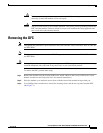
Installing the DFC
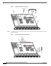
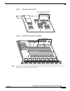
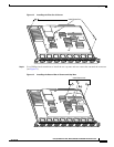
Figure 5 Mounting Holes on the DFC
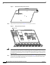
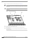
Figure 6 Male Standoff Locations on the Module
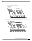
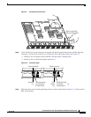
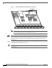
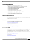
Step 5
Ensure that the connectors on the DFC are aligned with the connectors on the module. Figure 7 shows
the connectors on the underside of the DFC.
47084
Align with the male standoffs
on the module
WS-X5530
47083
S
T
A
T
U
S
L
IN
E
L
IN
E
1
1
2
L
IN
E
L
IN
E
3
4
L
IN
E
L
IN
E
5
6
L
IN
E
L
IN
E
7
8
L
IN
E
L
IN
E
9
10
L
IN
E
L
IN
E
11
12
L
IN
E
L
IN
E
13
14
L
IN
E
L
IN
E
15
16
2
3
4
5
6
7
8
9
10
11
12
13
14
15
16
Male standoffs