


18
Catalyst 6500 Series DFC, DFC3A, DFC3B, and DFC3BXL Installation Note
78-11627-04
Installing the DFC
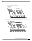
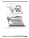
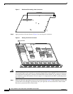
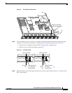
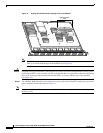
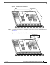
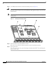
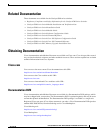
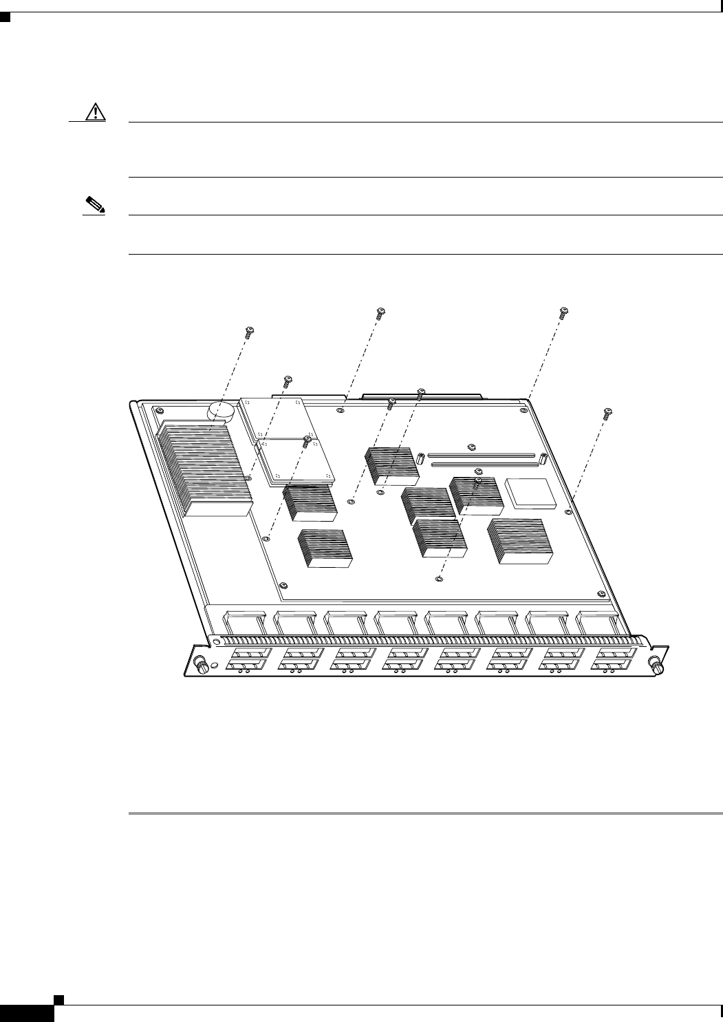
Step 12 Use a Phillips-head screwdriver to install the remaining screws (see Figure 14).
Caution Yo u must install screws in all available standoffs. The screws provide grounding between the DFC and
the module. Failure to install all screws will invalidate the safety approvals and pose a risk of fire and
electrical hazard.
Note You should visually verify that there are standoffs beneath the mounting holes before installing the
securing screws.
Figure 14 Installing the Remaining Screws
Step 13 Install the module in the Catalyst 6500 series switch.
Refer to the Catalyst 6500 Series Module Installation Guide for installation instructions.
Step 14 Power up the switch.
If the switch comes online, the system acknowledges the module and the DFC. The switch brings the
module and DFC online.
WS-X5530
47082
S
T
A
T
U
S
L
IN
E
L
IN
E
1
1
2
L
IN
E
L
IN
E
3
4
L
IN
E
L
IN
E
5
6
L
IN
E
L
IN
E
7
8
L
IN
E
L
IN
E
9
10
L
IN
E
L
IN
E
11
12
L
IN
E
L
IN
E
13
14
L
IN
E
L
IN
E
15
16
2
3
4
5
6
7
8
9
10
11
12
13
14
15
16