


12
Catalyst 6500 Series DFC, DFC3A, DFC3B, and DFC3BXL Installation Note
78-11627-04
Installing the DFC
Installing the DFC
Note Throughout this publication, unless otherwise noted, the term DFC refers to the DFC, DFC3A, DFC3B,
and DFC3BXL.
Note The figures in this procedure show the DFC. The procedure is the same for the DFC, DFC3A, DFC3B,
and DFC3BXL.
Caution During this procedure, wear grounding wrist straps to avoid ESD damage to the card. Do not directly
touch the backplane with your hand or any metal tool, or you could shock yourself.
To install the DFC on a fabric-enabled module, follow these steps:
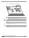
Step 1 Remove the module from the Catalyst 6500 series switch. (Refer to the Catalyst 6500 Series Module
Installation Guide for removal instructions.)
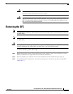
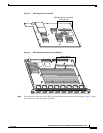
Step 2 Place the module on an antistatic mat or foam, with the front of the module facing toward you
(see Figure 6).
Step 3 Remove the DFC from its antistatic bag.
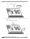
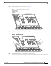
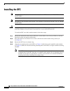
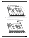
Step 4 Align the two mounting holes on the DFC (see Figure 5) with the two male standoffs on the module
(see Figure 6). Make sure that the remaining mounting holes on the DFC are aligned with the remaining
standoffs.
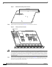
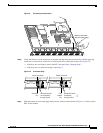
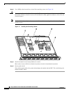
Note The DFC is designed to be installed on different modules; therefore, there may be more
mounting holes on the DFC than there are standoffs on the module. Not all mounting holes on
the DFC will be used in all installations. Visually verify that there are standoffs beneath the
mounting holes before installing the securing screws.