


Chapter 3 Operation of Front Panel Indicators
22 OL-30544-01
Initial Power On, Calibration, and Registration (AC
Power applied)
Writers: Duplicate this object and remove the original object from your book object.
Rename the topic description with the part number of your user guide.
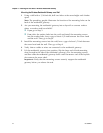
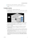
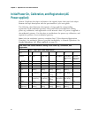
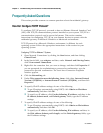
The following chart illustrates the sequence of steps and the corresponding
appearance of the residential gateway front panel LED status indicators during
power up, calibration, and registration on the network when AC power is applied to
the residential gateway. Use this chart to troubleshoot the power up, calibration, and
registration process of your residential gateway.
Note: After the residential gateway completes Step 7 (Data Network Registration
Complete), the residential gateway proceeds immediately to Normal Operations. See
Normal Operations (AC Power applied) (on page 23).
Front Panel LED Status Indicators During Initial Power Up, Calibration, and
Registration
Part 1, High Speed Data Registration
Step: 1 2 3 4 5 6 7
Front Panel
Indicator
Self
Test
Downstream
Scan
Downstream
Signal Lock
Ranging
Requesting
IP Address
Request High
Speed Data
Provisioning
File
Data
Network
Registration
Complete
1
POWER
On
On
On
On
On
On
On
2
DS
On
Blinking
On
On
On
On
On
3
US
On
Off
Off
Blinking
On
On
On
4
ONLINE
On
Off
Off
Off
Off
Blinking
On
5
ETHERNET
1-4
On
On or
Blinking
On or
Blinking
On or
Blinking
On or
Blinking
On or
Blinking
On
6
2.4G
On
Blinking or
Fast Blinking
Blinking or
Fast Blinking
Blinking or
Fast
Blinking
Blinking or
Fast Blinking
Blinking or
Fast Blinking
Blinking
7
5G
On
Blinking or
Fast Blinking
Blinking or
Fast Blinking
Blinking or
Fast
Blinking
Blinking or
Fast Blinking
Blinking or
Fast Blinking
Blinking
8
WPS
Off
Off or
Blinking
Off or
Blinking
Off or
Blinking
Off or
Blinking
Off or
Blinking
Off
9
MoCA
(Optional)
Off
Off, On, or
Blinking
Off, On, or
Blinking
Off, On, or
Blinking
Off, On, or
Blinking
Off, On, or
Blinking
On