


Configuring LAN Interfaces
Configuring a LAN Extender Interface
IC-56
Cisco IOS Interface Configuration Guide
Troubleshooting the LAN Extender
The primary means of troubleshooting the LAN Extender is by using the light emitting diodes (LEDs)
that are present on the chassis. This section will help you assist the remote user at the LAN Extender site
who can observe the LEDs.
The key to problem solving is to try to isolate the problem to a specific subsystem. By comparing what
the system is doing to what it should be doing, the task of isolating a problem is greatly simplified.
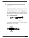
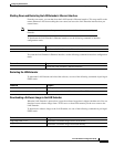
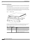
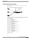
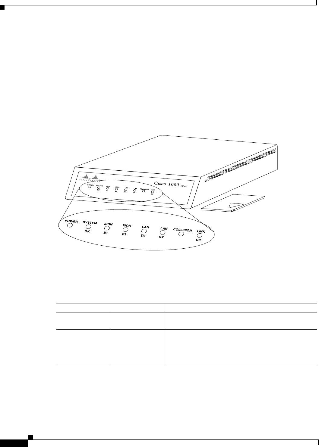
The Cisco 1000 series LAN Extender uses multiple LEDs to indicate its current operating condition. By
observing the LEDs, any fault conditions that the unit is encountering can be observed. The system LEDs
are located on the front panel of your LAN Extender (see Figure 9).
Figure 9 LAN Extender LEDs
When there is a problem with the LAN Extender, a user at the remote site should contact you and report
the condition of the LEDs located on the front panel of the LAN Extender. You can then use this
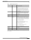
information to diagnose or verify the operation of the system. Table 4 explains the LEDs.
H2561
Table 4 LED Trouble Indicators
LED Condition Meaning
POWER On Steady Indicates that 12 V DC is being supplied to the LAN
Extender.
Off Indicates that power is not reaching the unit.
To correct the problem, make sure the power supply is
plugged into the wall receptacle and that the cable from the
power supply is connected to he unit.