


19
Cisco IE 3000 Switch Getting Started Guide
OL-16234-01
Cisco IE 3000 Switch Getting Started Guide
Warning
This product relies on the building’s installation for short-circuit (overcurrent)
protection. Ensure that the protective device is rated not greater than: 5A.
Statement 1005
Warning
Only trained and qualified personnel should be allowed to install, replace, or
service this equipment.
Statement 1030
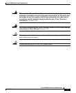
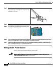
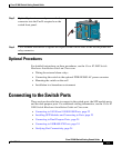
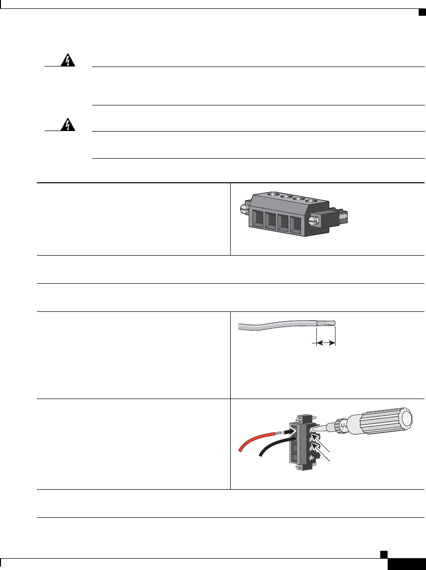
Step 1
Locate the power and relay connector.
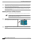
Step 2
Identify the positive and return DC power connections on the connector. The positive DC
power connection is labeled V, and the return is the adjacent connection labeled RT.
Step 3
Measure a strand of twisted-pair copper wire (18- to 20-AWG) long enough to connect to the
DC power source.
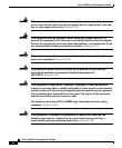
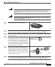
Step 4
Using an 18-gauge wire-stripping tool, strip
each of the two wires to 0.25 inch (6.3 mm) ±
0.02 inch (0.5 mm). Do not strip more than
0.27 inch (6.8 mm) of insulation from the
wire. Stripping more than the recommended
amount of wire can leave exposed wire from
the connector after installation.
Step 5
Insert the exposed part of the positive wire
into the connection labeled V and the exposed
part of the return wire into the connection
labeled RT. Make sure that you cannot see any
wire lead. Only wire with insulation should
extend from the connector.
Step 6
Use a ratcheting torque flathead screwdriver to torque the power and relay connector captive
screws (above the installed wire leads) to 2 in-lb, the maximum recommended torque.
201815
RT
A
V
A
0
.27 inch (6.6 mm)
119591
VRTA A
202330
RT
V