


15
RSP4+ Bootflash Memory Upgrade to 16MB Installation and Configuration Guide
78-12288-02
Installing the RSP4+
Installing the RSP4+
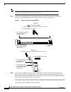
Follow the steps below to reinstall the RSP4+ that was removed.
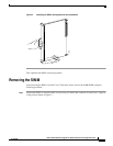
Step 1 Hold the RSP4+ handle with one hand and place your other hand under the carrier to support the
RSP4+ and guide it into the slot. (See Figure 2.) Avoid touching the card or any connector pins.
Caution To prevent ESD damage, handle the RSP4+ by the handles and carrier edges only.
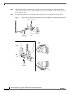
Step 2 Place the back of the RSP4+ in the slot and align the notch on the carrier with the groove in the slot.
(See Figure 1.)
Step 3 While keeping the RSP4+ parallel to the backplane, carefully slide it into the slot until the back of the
faceplate makes contact with the ejector levers, and then stop. (See b in Figure 1.)
Caution Use the ejector levers to remove or install the RSP4+. Failure to do so can cause erroneous
system error messages indicating a board failure.
Step 4 Using your thumbs, simultaneously push both ejector levers inward until the RSP4+ is pushed entirely
into its slot. (See c in Figure 1.)
Step 5 Tighten both captive installation screws.
Step 6 Reconnect the cables to the RSP4+.
This completes theRSP4+ installation procedure.
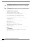
Loading and Configuring the Bootflash Image
Using the steps in this procedure, you will:
• Enable the router to enter privileged mode
• Confirm the new bootflash size
• Format the bootflash
• Copy the rsp-boot image onto the bootflash
• Confirm that the image has been copied to bootflash
• Modify the configuration file to reboot using the new bootflash image
• Configure the router to use the bootloader image in bootflash
• Save the configuration
• Confirm that the configuration reflects the new bootloader image