


Send documentation comments to nexus5kdocs@cisco.com.
1-49
Cisco Nexus 5000 Series Hardware Installation Guide
OL-15902-01
Chapter 1 Overview
Cisco Nexus 5000 Platform Switches
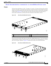
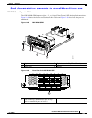
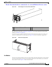
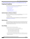
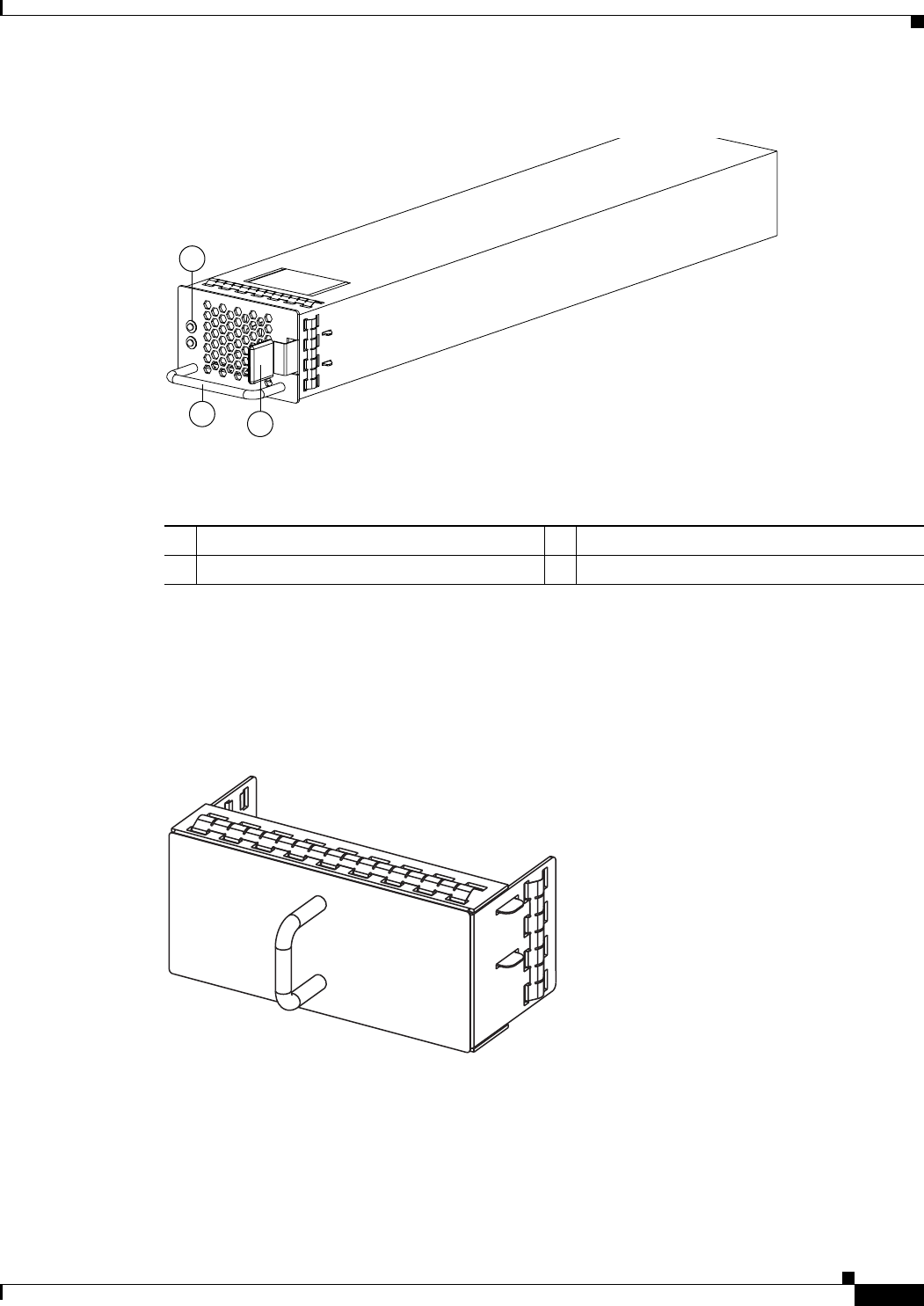
Figure 1-55 Power Supply for the Cisco Nexus 5010 Switch
For information on the LEDs see Table D-1 on page D-2. To see what combinations of these LEDs
indicate, see Table D-2 on page D-3.
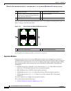
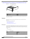
If you have one power supply installed in the chassis, but the other power supply slot is empty, you
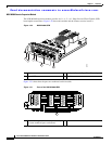
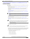
should use a blank panel to cover the empty slot. Figure 1-56 shows a blank power supply panel.
Figure 1-56 Blank Power Supply Panel
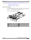
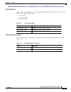
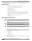
Fan Modules
The Cisco Nexus 5010 switch has slots for two fans modules. Each fan module houses six fans and each
uses front to back airflow. If you insert 2 fan modules (with 6 fans in each module), your switch will
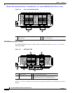
have a total of 12 fans. Figure 1-26 shows the fan module.
1
2
3
189955
1 FAIL (top) and OK (bottom) LEDs 3 Release latch
2 Handle
186854