


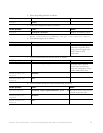

CASSATT ACTIVE RESPONSE CONTROL NODE AND NETWORK SWITCH CABLING EXAMPLE 17
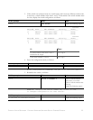
application nodes. Note that detailed instructions for adding application nodes are in a
separate document, which you should consult when you are ready to cable application nodes
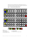
into your Cassatt Active Response environment. (Figure 1 highlights the control node and
network switches, but also suggests application node cabling.)
Figure 1 Switch Panel and Control Node Cabling
C2-1
C2-P
C2-2
Gb 2
Gb1
Control node 2
C1-1
N9-1N5-1
ISL-1
N21-1
N12-P
N3-P
C2-1
N11-1
N7-1N3-1
GW-1 N16-PN23-1
N8-P
1
2
3
4
5
Switch stack 1
N20-P
N13-1
N15-1
N17-1
N19-1
N10-1N6-1
ISL-2
N11-P
N1-P
N12-1N8-1N4-1
N15-P
N23-P
N7-P C2-P
N19-P
N14-1
N16-1
N18-1
N20-1
Switch stack 2
Control node 1
Switch 1
Switch 2
Switch 3Switch 4
79
11 13 15
17
19 21
23
6
8
10 12
14
16 18
20
22 24
1
3
5
7
9
11 13 15
17 19
21
23
2
46
810
12 14 16 18 20 22
24
C1-2
N9-2N5-2
ISL-1
N21-2
N10-P
N4-P
C2-2
N11-2
N7-2N3-2
GW-2
N22-P
N23-2
N6-P
1
2
3
4
5
N18-P
N13-2
N15-2
N17-2
N19-2
N10-2N6-2
ISL-2
N9-P N2-P
N14-2N10-2N4-2
N13-P
N21-P
C1-P
N17-P
N14-2
N16-2
N18-2
N20-2
79
11 13 15 17
19 21
23
6
8
10 12
14
16 18
20
22 24
1
3
5
7
9
11 13 15
17 19
21
23
2
46
810
12 14 16 18 20 22
24
C1-1
C1-P
C1-2
Gb 2
Gb1
N14-P
N5-P
N1-1
N1-2
N2-1
N2-2
N22-1
N22-2
Legend:
Blue = Gateway (GW) N
n-1 = Application node NIC
Yellow = Cisco interswitch link (ISL) N
n-2 = Application node NIC
Green = Control node (C) N
n-P = Application node remote management controller
Red = Remote management controller