


1-7
Cisco Building Broadband Service Manager 5.1 Software Configuration Guide
OL-1566-01
Chapter 1 Introduction
Configuration Sequence
Fully routed networks are supported by associating all switches with routers other than router
number 0. All switches are on networks attached to routers that are reachable through gateways on
the BBSM Server internal network.
For routed networks, enter information about the routers within the BBSM internal network.
• Mixed (bridged and routed) networks
Mixed networks include a bridged network and one or more routed networks. Some switches are on
the BBSM Server internal network and others can be reached through gateways on the internal
network.
Use the Routers web page to configure routes to the switches and routes to the client computers (guests)
attached to the switches.
The BBSM Server, which is the “router” all traffic must pass through before reaching the Internet, is
assigned router number 0. This is predefined and always has an IP address of 127.0.0.1. It is a loopback
address that the BBSM Server uses to communicate with itself.
Note Review installation requirements to determine the configuration applicable for your installation.
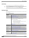
Configuration Sequence
The following procedure is a high level view of the configuration process for a BBSM system. You
perform these steps on either a factory-installed or customer-installed BBSM Server.
Note For a customer-installed BBSM Server, refer to the Cisco Building Broadband Service Manager and
Director Installation Guide for details on how to install the software.
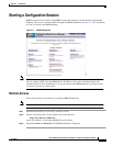
1. Launch WEBconfig from the BBSM Dashboard to define the system settings for the BBSM Server.
2. During the basic configuration, work from left to right on the WEBconfig button bar as you:
a. Define the settings that apply on the server level (IP addresses).
b. Configure the sites managed by the server.
c. Define the network components that make up the site (for example, switches, routers, or other
equipment).
d. Generate a Port Map for each site in the network topology.
e. The Port Map contains artificial guest room numbers mapped to ports. This map is used to
associate ports to actual room numbers throughout each building.
f. Modify individual ports to reflect any specific per-port settings.
3. Select the appropriate policy for each port or ports.
4. Configure any billing related systems for the system accounting policies. Refer to Chapter 6,
“Pricing and Page Set Management.”
5. Configure BBSM for bandwidth allocation if appropriate. Refer to Chapter 7, “Bandwidth
Management.”
6. Connect BBSM to a PMS if appropriate. Refer to Chapter 5, “Making the Property Management
System Connection.”