


1-13
PA-4T Synchronous Serial Port Adapter Installation and Configuration
OL-3560-02
Chapter 1 Overview
Port Adapter Slot Locations on the Supported Platforms
Port Adapter Slot Locations on the Supported Platforms
This section discusses port adapter slot locations on the supported platforms. The illustrations that
follow summarize slot location conventions on each platform.
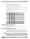
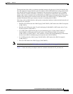
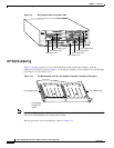
Cisco 7200 Series Router Slot Numbering
Figure 1-9 shows a Cisco 7206 with port adapters installed. In the Cisco 7206, port adapter slot 1 is in
the lower left position, and port adapter slot 6 is in the upper right position. (The Cisco 7202 and Cisco
7204 are not shown; however, the PA-4T can be installed in any available port adapter slot.)
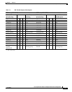
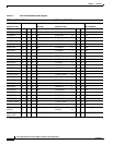
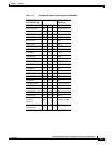
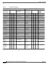
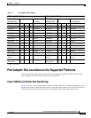
Table 1-7 X.21 Adapter Cable Signals
DTE Cable (CAB-X21MT=) DCE Cable (CAB-X21FC=)
VIP End, HD
1
60-Position Plug
1. HD = high density.
Network End,
DB-15 Plug
VIP End, HD
60-Position Plug
Network End,
DB-15 Receptacle
Signal Pin Pin Signal Signal Pin Pin Signal
Shield ground 46 1 Shield ground Shield ground 46 1 Shield ground
TxD/RxD+ 11 —> 2 Transmit+ RxD/TxD+ 11 —> 2 Transmit+
TxD/RxD– 12 —> 9 Transmit– RxD/TxD– 12 —> 9 Transmit–
RTS/CTS+ 9 —> 3 Control+ CTS/RTS+ 9 —> 3 Control+
RTS/CTS – 10 —> 10 Control– CTS/RTS – 10 —> 10 Control–
RxD/TxD+ 28 <— 4 Receive+ TxD/RxD+ 28 <— 4 Receive+
RxD/TxD– 27 <— 11 Receive– TxD/RxD– 27 <— 11 Receive–
CTS/RTS+ 1 <— 5 Indication+ RTS/CTS+ 1 <— 5 Indication+
CTS/RTS – 2 <— 12 Indication– RTS/CTS– 2 <— 12 Indication–
RxC/TxCE+ 26 <— 6 Timing+ TxC/RxC+ 26 <— 6 Timing+
RxC/TxCE– 25 <— 13 Timing– TxC/RxC – 25 <— 13 Timing–
Circuit ground 15 8 Circuit ground Circuit ground 15 8 Circuit ground
Ground
Mode_2
48
47
Shorting group Ground
Mode_2
48
47
Shorting
group
Ground
Mode_DCE
51
52
Shorting group Ground
Mode_DCE
51
52