


1-16
PA-4T Synchronous Serial Port Adapter Installation and Configuration
OL-3560-02
Chapter 1 Overview
Identifying Interface Addresses
Cisco 7200 Series Routers Interface Addresses
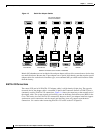
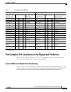
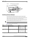
This section describes how to identify the interface addresses used for the PA-4T in Cisco 7200 series
routers. The interface address is composed of a two-part number in the format
port-adapter-slot-number/interface-port-number. See Table 1-8 for the interface address format.
In Cisco 7200 series routers, port adapter slots are numbered from the lower left to the upper right,
beginning with port adapter slot 1 and continuing through port adapter slot 2 for the Cisco 7202, slot 4
for the Cisco 7204, and slot 6 for the Cisco 7206. (Port adapter slot 0 is reserved for the optional Fast
Ethernet port on the I/O controller—if present.)
The interface addresses of the interfaces on the PA-4T in port adapter slot 1 are
1/0 through 1/7 (port adapter slot 1 and interfaces 0 through 7). If the PA-4T was in port adapter slot 4,
these same interfaces would be numbered 4/0 through 4/7 (port adapter slot 4 and interfaces
0 through 3).
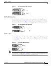
VIP Interface Addresses
This section describes how to identify the interface addresses used for the PA-4T on a VIP in Cisco 7500
series routers.
Note Although the processor slots in the 7-slot Cisco 7507, the 13-slot, and the 13-slot Cisco 7576 are
vertically oriented and those in the 5-slot Cisco 7505 are horizontally oriented, all Cisco 7500 series
routers use the same method for slot and port numbering.
See Table 1-8 for the interface address format. The interface address is composed of a three-part number
in the format interface-processor-slot-number/port-adapter-slot-number/interface-port-number.
If the VIP is inserted in interface processor slot 3, then the interface addresses of the PA-4T are 3/1/0
through 3/1/3 (interface processor slot 3, port adapter slot 1, and interfaces 0 through 3). If the
port adapter was in port adapter slot 0 on the VIP, these same interface addresses would be numbered
3/0/0 through 3/0/3.
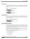
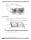
Note If you remove the VIP with the PA-4T (shown in Figure 1-11) from interface processor
slot 3 and install it in interface processor slot 2, the interface addresses become 2/1/0 through 2/1/3.