


3-4
Cisco Access Router Manager User Guide
OL-3597-01
Chapter 3 Deploying and Discovering Objects
Automatic Discovery
inserted into a NM–2FE2W network module in slot 1 (i.e., NM–2FE2W–1), occupies a subslot and
would be named WIC–2T–1–0 if it were in slot 1 subslot 0. It would be named WIC–2T–1–1 if it were
in slot 1 subslot 1.
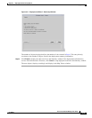
The interfaces on a network module which contains subslots, such as the NM–2FE2W module, follows
two different interface naming conventions. If the NM–2FE2W is in slot 1 (i.e., NM–2FE2W–1), the
interfaces directly on the module are named FastEthernet 1–0 and FastEthernet 1–1 indicating the
interface type followed by the slot–port number. This interface naming convention is exactly the same
as that described in the preceding paragraphs. If the same NM–2FE2W module in slot 1 also contains an
interface card in subslot 0, for example a WIC–2T (i.e., WIC–2T–1–0), the associated interfaces would
be named Serial 1–0 and Serial 1–1. In this case, notice that the digits following the interface type
indicate the slot–port location and do not cite the subslot number of the WIC immediately above the
serial interface in the physical hierarchy. If there is another WIC–2T in subslot 1 (i.e., WIC–2T–1–1),
the associated interfaces are also named Serial 1–0 and Serial 1–1. Again, the naming convention does
not reflect the subslot number and reads the slot number from the parenting network module. The
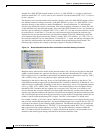
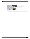
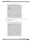
following figure displays this example as the objects appear in the physical hierarchy.
Figure 3-2 Network Module/Interface Port and Interface Card/Port Naming Convention
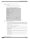
Managed objects which reside outside of the network module slots, directly on the chassis rather than
within a network module slot, appear in the Physical view hierarchy beneath the CPU–0 object. The
CPU–0 object serves as a container for the external Fast Ethernet port(s) and interface card (e.g., WICs,
VICs, VWICs) slot(s), and is not a physical object within the device itself.
Depending on the chassis, there may be one to four Fast Ethernet ports directly on the chassis. The
related Ethernet interfaces appear directly beneath the CPU–0 module as Ethernet 0–0, Ethernet 0–1, etc.
when discovered. Additionally, depending on the chassis, there may be zero to two supported interface
card (e.g., WICs, VICs, VWICs) slots. The interface cards which fill these slots also appear directly
beneath the CPU–0 module and may support one or two ports each. The ports on an interface card
discover beneath the associated interface card object within the hierarchy, and the name includes the
interface type and port number on the interface card. Similar to the naming convention of interface cards
and associated ports previously described, the interface card slot number is disregarded. Instead, the slot
number is derived from the parenting CPU–0 object. The CPU–0 slot number is a default value.
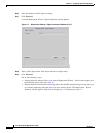
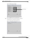
For example, consider a Cisco 2611 chassis which can accommodate up to two external interface cards
and up to two external Ethernet interfaces. Say that both Ethernet ports are occupied and one WIC–2T
is present in the chassis (as the following figure illustrates). The Ethernet interfaces are automatically
named Ethernet 0–0 and Ethernet 0–1. The WIC–2T is automatically named WIC–2T–0–1, indicating
that it is present in the external interface card slot 1. The possible interfaces contained within the
WIC–2T could be Serial 0–0 and Serial 0–1. Again, notice that the interface card slot number is not
included in the interface port naming convention on the external interface cards.