


18
Catalyst 6509-NEB Switch and Cisco OSR-7609 Router Upgrade Note
78-16162-02
Replacing the Supervisor Engine
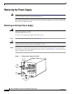
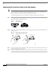
Step 3 Loosen the two captive installation screws on the supervisor engine.
Step 4 Place your thumbs on the ejector levers located at the top and bottom of the supervisor engine, and
simultaneously rotate the levers outward to unseat the supervisor engine from the backplane connector.
Step 5 Grasp the edges of the supervisor engine, and slide the supervisor engine straight out of the slot. Do not
touch the module circuitry.
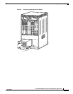
Step 6 Place the supervisor engine on an antistatic mat or antistatic foam.
Step 7 If the slot is to remain empty, install a module filler plate to keep dust out of the chassis and to maintain
proper airflow through the chassis.
Installing the Supervisor Engine
This section describes how to install the Supervisor Engine 720 or the Supervisor Engine 32 in the
Catalyst 6509-NEB switch and the Cisco OSR-7609 Router.
Caution To prevent ESD damage, handle modules by the carrier edges only.
Note The Supervisor Engine 720 or Supervisor Engine 32 must be installed in slot 5 or 6 of the Catalyst
6509NEB or Cisco OSR7609 chassis.
To install the supervisor engine in the chassis, perform these steps:
Step 1 Choose a slot for the supervisor engine.
Step 2 Verify that there is enough clearance to accommodate any interface equipment that you will connect
directly to the supervisor engine ports. If possible, place modules between empty slots that contain only
module filler plates.
Step 3 Verify that the captive installation screws are tightened on all modules installed in the chassis. This
assures that the EMI gaskets on all modules are fully compressed in order to maximize the opening space
for the new module or the replacement module.
Note If the captive installation screws are loose, the EMI gaskets on the installed modules will push
adjacent modules toward the open slot, reducing the opening size and making it difficult to
install the replacement module.
Step 4 Remove the module filler plate by removing the two Phillips pan-head screws from the filler plate. To
remove a module, see the “Removing the Supervisor Engine” section on page 17.
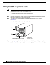
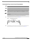
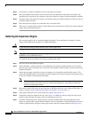
Step 5 Fully open both ejector levers on the supervisor engine. (See Figure 15.)
Step 6 Position the supervisor engine in the slot. (See Figure 15.) Make sure that you align the sides of the
module carrier with the slot guides on the top and bottom of the slot.
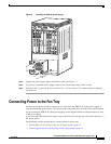
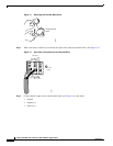
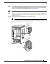
Step 7 Carefully slide the supervisor engine into the slot until the EMI gasket along the right edge of the
supervisor engine makes contact with the module in the slot adjacent to it and both ejector levers have
closed to approximately 45 degrees with respect to the supervisor engine faceplate. (See Figure 16.)