


1-7
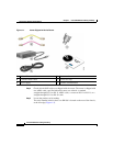
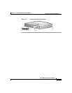
Cisco SB 106 Router Cabling and Setup
78-16773-01
Chapter 1 Cisco SB 106 Router Cabling and Setup
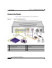
Connect the Router
Follow these steps to connect the router to the power supply, your local network,
and your service provider’s network:
Step 1 If you are connecting more than 4 PCs to the router, connect the router to a switch
or hub using a yellow Ethernet cable, as shown in Figure 1-3.
Step 2 To connect a PC directly to your router, do so as shown in Figure 1-3. Turn the PC
off so that it will obtain an IP address from the router when it is turned on. You
can connect additional PCs to the remaining numbered Ethernet ports.
Step 3 The console port is a service port to which you can connect a terminal or PC in
order to configure the software by using the command-line interface (CLI) or to
troubleshoot problems with the router. If you want access to the router console,
connect a PC or terminal to the console port.
Step 4 (Optional) For remote management, you can connect the ISDN S/T port to a
Network Termination (NT1) box or an ADSL splitter using the orange ISDN S/T
cable (ordered separately).
Step 5 Connect the the ADSL cable to the ADSLoISDN port on the router and to the
ADSL splitter or wall socket. If you are using an ADSL splitter, connect the
splitter to the wall socket using a Category 5 unshielded twisted-pair cable.
Step 6 Connect power to the router as shown in Figure 1-3 and turn on the router. Be sure
to use the power supply that was shipped with the router.
Step 7 Attach the power lock clip to the router enclosure by attaching the clip to the
power cord, sliding the clip to the end of the power connector, and snapping the
latches into the holes on the enclosure.
Warning
The device is designed to work with TN power systems.