


1-4
Cisco VG350 Voice Gateway Hardware Installation Guide
OL-25970-01
Chapter 1 Overview of the Cisco VG350 Voice Gateway
Physical Description and LEDs
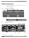
Physical Description and LEDs
LED Indicators
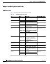
Table 1-3 describes the LED indicators for the Cisco VG350.
Table 1-3 LED Indicators for Cisco VG350
LED Color Description Location on the VG350
PS/PS1 Green System is running. Front bezel
Amber System is not running.
PS2 Green System is running. Front bezel
Amber System is not running.
AC OK Green AC power connected. Front bezel
Off No AC power connected
RPS Green System is running on external
RPS power supply.
—
SYS Solid green Solid green indicates normal
operation.
Front bezel
Blinking green System is booting or is in ROM
monitor mode.
Amber System error.
Off Power is off or system board is
faulty.
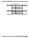
ACT Solid or
blinking green
Solid or blinking indicates
packet activity between the
forwarding and routing engine
and any I/O port.
Front bezel
Off No packet transfers are
occurring.
RJ-45 CON Green Serial console is active. Back panel
USB CON Green USB console is active. Back panel
GE: Link Green Solid green indicates the
Ethernet port has a link partner.
Back panel
SFP S Blinking green Blinking frequency indicates
port speed. See the definition for
the S LED.
Back panel
SFP EN Off Not present. Back panel
Green Present and enabled.
Amber Present with failure.