


3
Installing the Cisco WAE Inline Network Adapter
OL-12480-03
Product Overview
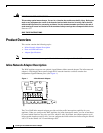
The WAAS software defines two new interface types: A group interface that represents an inline pair
grouping and a port interface that represents the individual port. These interfaces are referred to as
inlineGroup and inlinePort.
InlineGroup interfaces are numbered using the format slot/group. The slot number is the slot in which
the adapter is inserted. (In the WAE 500 series and 600 series appliances, you must install the adapter in
slot 1 only.) The group number is either 0 or 1 (each adapter has 2 group pairs). The group number is
displayed on the adapter label.
InlinePort interfaces are numbered slot/group/lan or slot/group/wan. The last attribute is the LAN or
WAN designator.
The inline network adapter also includes an onboard programmable watch dog timer (WDT) controller
that allows you to set the time to wait after a failure event, such as a power outage or a kernel crash,
before the unit begins to operate in mechanical bypass mode. In mechanical bypass mode, traffic is
bridged between the LAN and WAN ports of each group. Mechanical bypass mode prevents the WAE
from becoming a single point of failure and allows traffic to continue to flow between the router and the
client while it passes through an unresponsive WAE without being processed.
For more information about configuring the inline network adapter, see the Cisco Wide Area Application
Services Configuration Guide.
Ports and LED Indicators
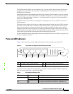
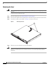
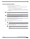
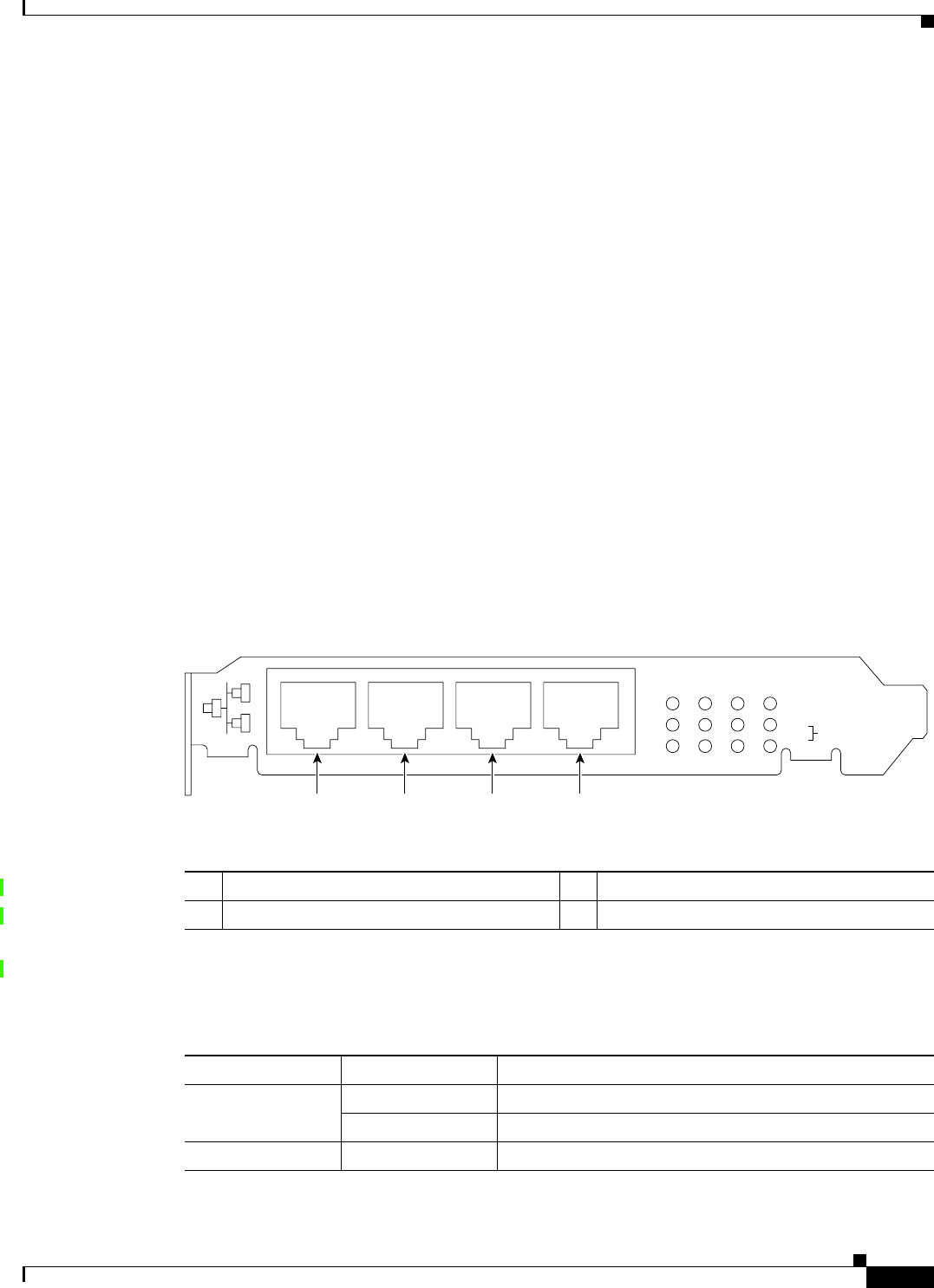
Figure 2 shows the inline network adapter port numbers, interface designations, and LEDs.
Figure 2 Inline Network Adapter Port Numbering and LEDs
The inline network adapter has three LEDs that correspond to each port (the W1 LEDs correspond to
Port W1, and so forth). Table 1 describes the LEDs.
W1 Port WAN1; Group 1 WAN interface L1 Port LAN1; Group 1 LAN interface
W0 Port WAN0; Group 0 WAN interface L0 Port LAN0: Group 0 LAN interface
W1 L1 W0 L0
LINK/ACT
100
1000
BYPASS
W1 L1 W0 L0
272072
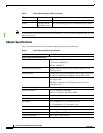
Table 1 Inline Network Adapter LEDs
LEDs State Description
Link / Activity On The 10/100/1000BASE-T interface is receiving power.
Blinking The Ethernet link is transmitting data.
100 On The speed of the Ethernet connection is 100BASE-TX.