


5
Installing the NetFlow Services Card
78-15214-01
Installing the NetFlow Services Card
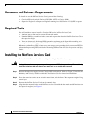
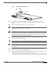
Figure 1 Aligning the NetFlow Services Card
Step 5
Ensure that the connectors on the NetFlow Services Card are aligned with the connectors on
the supervisor engine, which should happen automatically when the mounting holes are correctly
aligned.
Step 6 Apply pressure to the NetFlow Services Card to seat the connectors.
Caution Use care not to damage the connectors on the supervisor engine. If you damage a connector, you will
have to return the supervisor engine to Cisco for repair.
Caution Using the screws to seat the NetFlow Services Card could warp the card. Before you install and tighten
the securing screws, ensure that the NetFlow Services Card is fully seated by visually verifying that there
is no gap between the male and female keys on the connectors and that the bottom of the NetFlow
Services Card is in contact with the tops of the standoffs.
Step 7 Using a Phillips screwdriver, install two screws at the front of the NetFlow Services Card and one screw
at the power heat sink as shown in Figure 1.
Note Before installing the securing screws, visually verify that there are standoffs beneath the mounting holes.
Caution You must install all the screws. The screws provide grounding between the NetFlow Services Card and
the module. Failure to install all screws will invalidate the safety approvals and pose a risk of fire and
electrical hazard.
Step 8 Install the supervisor engine in the Catalyst 4500 series switch. (Refer to the Catalyst 4500 Series
Module Installation Guide for installation instructions.)
Step 9 Power up the switch. If the switch comes online normally, the system has acknowledged the supervisor
engine and the NetFlow Services Card and has brought them online.
84384
Heat sink