


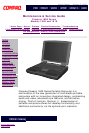
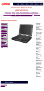

Maintenance & Service Guide
Presario 1800 Series
Models: 1805 and 1810
| Home Page | Notice | Preface | Product Description | Troubleshooting
Illustrated Parts Catalog | Removal & Replacement Procedures | Specifications
Pin Assignments | Battery Pack Operations
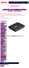
Connector Pin Assignments
This appendix provides connector pin assignment tables for Compaq Presario 1800
Series Portable Computers. For more information on connectors, refer to the section
on Rear Connectors.
NOTE: The signals in all tables of this appendix are considered active high unless
otherwise indicated by an asterisk (*).
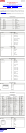
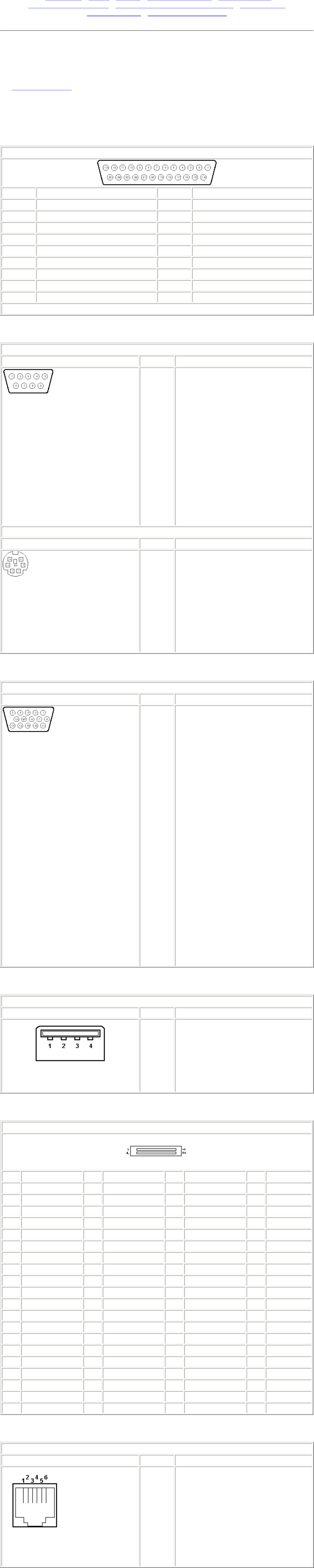
Parallel Connector
Pin Signal Pin Signal
1 Strobe* 10 Acknowledge*
2 Data Bit 0 11 Busy
3 Data Bit 1 12 Paper Out
4 Data Bit 2 13 Select
5 Data Bit 3 14 Auto Linefeed*
6 Data Bit 4 15 Error*
7 Data Bit 5 16 Initialize Printer*
8 Data Bit 6 17 Select In*
9 Data Bit 7 18-25 Signal Ground
* = Active low
Serial Connector
Connector Pin Signal
1
2
3
4
5
6
7
8
9
Carrier Detect
Receive Data
Transmit Data
Data Terminal Ready
Signal Ground
Data Set Ready
Ready to Send
Clear to Send
Ring Indicator
Keyboard/Mouse
Connector Pin Signal
1
2
3
4
5
6
Data
Not defined
Ground
+5 VDC
Clock
Not defined
External VGA Monitor
Connector Pin Signal
1
2
3
4
5
6
7
8
9
10
11
12
13
14
15
Red Analog
Green Analog
Blue Analog
Not connected
Ground
Ground Analog
Ground Analog
Ground Analog
Not connected
Ground
Monitor Detect
DDC2B Data
Horizontal Sync
Vertical Sync
DDC2B Clock
Universal Serial Bus
Connector Pin Signal
1
Ground
2 D+
3 D-
4 Power
Port Replicator
Pin Signal Pin Signal Pin Signal Pin Signal
1 N.C. 21 Printer Data 0 41 N.C. 61 CTS
2 N.C. 22 Printer Data 1 42 N.C. 62 DCD
3 Kb Clk 1 23 Printer Data 2 43 Switch A 63 DSR
4 Joystick Data A 24 Printer Data 3 44 Switch B 64 TXD
5 Kb Data 1 25 Printer Data 4 45 Switch C 65 RTS
6 Joystick Data B 26 Printer Data 5 46 Switch D 66 N.C.
7 Kb Clk 2 27 Printer Data 6 47 N.C. 67 Detect
8 Joystick Data C 28 Printer Data 7 48 MIDI In 68 N.C.
9 Kb Data 2 29 USB 0 - 49 MIDI Out 69 V. Sync
10 Joystick Data D 30 USB 0 + 50 +5V 70 Ground
11 Lp Select In 31 USB 1 - 51 +5V 71 H. Sync
12 Lp Paper End 32 USB 1+ 52 N.C. 72 Ground
13 Lp Initialize 33 Adapter In 53 N.C. 73 Blue
14 Lp Busy 34 Adapter In 54 N.C. 74 Ground
15 Lp Error 35 Adapter In 55 N.C. 75 Green
16 Lp Ack 36 Adapter In 56 Dock ID - 76 Ground
17 Lp Auto Feed 37 Adapter In 57 RXD 77 Red
18 Lp Strobe 38 Adapter In 58 Lp Select 78 Ground
19 DDC2BC 39 N.C. 59 RI 79 N.C.
20 DDC2BD 40 N.C. 60 DTR 80 N.C.
Modem
Connector Pin Signal
1
2
3
4
5
6
Unused
Unused
Tip
Ring
Unused
Unused
privacy statement
legal notices