


5–28 Maintenance and Service Guide
Removal and Replacement Procedures
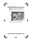
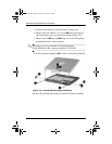
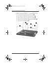
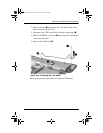
3. Remove the following TM2.5 × 7.0 screws (Figure 5-22):
❏ Four screws along the notebook front edge 1
❏ Two screws on each side of the hard drive bay 2
❏ Three screws on the rear edge of the notebook 3
❏ One screw in the memory expansion compartment 4
❏ One screw near the fan vent 5
Figure 5-22. Removing the Top Cover Screws
307503-003.book Page 28 Friday, April 4, 2003 3:37 PM